
Instruction Manual
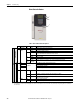
Table Of Contents
- PowerFlex 700S High Performance AC Drive - Phase II Control, Programming Manual
- Summary of Changes
- Table of Contents
- Preface
- Chapter 1 - Drive Start-Up
- Chapter 2 - Programming and Parameters
- Chapter 3 - Troubleshooting
- Appendix A - Human Interface Module Overview
- Appendix B - Application Notes
- Appendix C - Control Block Diagrams
- Appendix D - PowerFlex 700S Permanent Magnet Motor Specifications
- Appendix E - ATEX Approved PowerFlex 700S, Phase II Drives in Group II Category (2) Applications with ATEX Approved Motors
- Appendix F - History of Changes
- Index
- Back Cover
Rockwell Automation Publication 20D-PM001C-EN-P - July 2013 139
Chapter 3
Troubleshooting
This chapter provides information to guide you in troubleshooting the
PowerFlex 700S drive. A list and description of drive faults (with possible
solutions, when applicable) and alarms is included.
Status Indicators
The condition or state of your drive and DriveLogix controller (if installed) is
constantly monitored. Any changes will be indicated through the front panel
LEDs and/or the HIM (if present). See Drive Status Indicators on page 140
for
more information. The DriveLogix option also provides a RUN LED and the
controller LEDs that indicate the state of the controller. See DriveLogix5730
Controller Status Indicators on page 141
for more information.
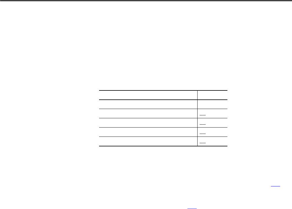
Topic Page
Status Indicators Below
HIM Indication of a Fault 144
Manually Clearing Faults 144
Fault and Alarm Types 144
Fault/Alarm Descriptions 145