
Maintenance Stand User Manual


Publication PFLEX-IN014B-EN-P
PowerFlex® 700S and 700H Frame 10…14 Drives
Maintenance Stand
Installation Instructions
Introduction
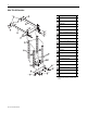
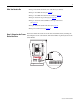
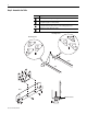
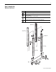
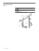
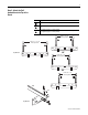
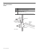
Use this document to assemble the maintenance stand and attach it to a
PowerFlex 700S or 700H frame 10…14 drive, which contains a power structure
you want to remove. For complete information on removing the power structure
from the drive enclosure, refer to the appropriate Hardware Service Manual for
your drive:
The publications listed above are available online at
www.rockwellautomation.com/literature
.
U.S. Allen-Bradley Drives Technical Support:
• Tel: (1) 262.512.8176
• Fax: (1) 262.512.2222
• Email: support@drives.ra.rockwell.com
• Online at: www.ab.com/support/abdrives
.
Title Publication
Hardware Service Manual - PowerFlex 700S and 700H Frame 10 Drives PFLEX-TG002
Hardware Service Manual - PowerFlex 700S and 700H Frame 11 Drives PFLEX-TG003
Hardware Service Manual - PowerFlex 700S and 700H Frame 12 Drives PFLEX-TG004
Hardware Service Manual - PowerFlex 700S and 700H Frame 13 Drives PFLEX-TG005
Hardware Service Manual - PowerFlex 700S and 700H Frame 14 Drives PFLEX-TG006
ATTENTION: This maintenance stand is intended for removing
and installing power structures for frame 10…14 PowerFlex 700S
and 700H drives installed in standard Rittal enclosures only. Using it
for other purposes may lead to personal injury or equipment damage.
Do not use it for any other purpose.