
Manual

39
Publication 20C-IN001D-EN-P
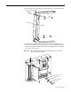
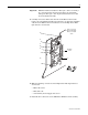
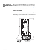
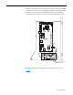
3. Connect the twisted pair wires from connector J1 on the 24V Common Mode
Filter board to connector J5 on the High Power Fiber Optic Interface board.
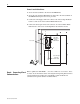
4. Connect the 24V power supply cable from connector J8 on the Voltage
Feedback board to connector J5 on the 24V Common Mode Filter board.
5. Continue with Step 8 “Connecting I/O and Communications” on page
page 40
.
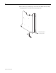
24V Supply cable to J8 on Voltage
Feedback circuit board
J5
J1
J5