
Manual


Publication 20C-IN001D-EN-P
2
What This Kit Includes
• Phase II control assembly mounting plate, bracket and hardware
• 40 conductor ribbon cable
• 30 conductor ribbon cable
• Status cable
• 10 conductor ribbon cable for frame 9 drives
• 10 conductor ribbon cable for frame 10…14 drives
• Power Interface circuit board and hardware
• Voltage Feedback circuit board and hardware
• Phase II control cassette (required, ordered separately)
• 24V Common Mode Filter circuit board and hardware for frame 10…14
drives
• Twisted pair wires and connectors for 24V Common Mode Filter circuit
board for frame 10…14 drives
• EMI shield and hardware for frame 10…14 drives
Tools That You Need
• Phillips
®
screwdriver
• POZIDRIV
®
screwdriver
• Torx Head screwdriver
Phillips
®
and POZIDRIV
®
are registered trademarks of Phillips Screw
Company.
What You Need to Do
The steps to complete the PowerFlex® 700H to 700S Phase II control
conversion are different for frame 9 size drives versus frame 10…14 size drives.
Refer to “Frame 9 Conversions Only
” for frame 9 conversion instructions. Refer
to Frame 10…14 Conversions Only
on page 17 for frame 10…14 conversion
instructions.
Frame 9 Conversions Only
Complete these instructions if you are converting a PowerFlex frame 9 size
drive only:
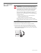
❐ Step 1: Remove power from the drive
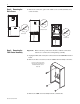
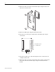
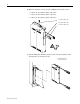
❐ Step 2: Remove drive covers
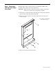
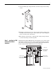
❐ Step 3: Remove 700H control assembly
❐ Step 4: Remove 700H Fiber Optic Adapter circuit board
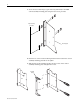
❐ Step 5: Install 700S Phase II Main Control assembly
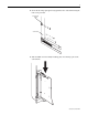
❐ Step 6: Install Voltage Feedback circuit board
❐ Step 7: Install High Power Fiber Optic Interface circuit board
❐ Step 8: Install chassis fan
❐ Step 9: Connecting I/O and Communications
❐ Step 10: Document change