
Manual

17
Publication 20C-IN001D-EN-P
Frame 10…14 Conversions
Only
Complete these instructions if you are converting a PowerFlex frame 10…14
size drive:
❐ Step 1: Remove power from drive
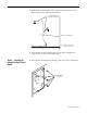
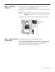
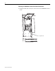
❐ Step 2: Open drive
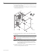
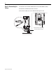
❐ Step 3: Remove 700H Control assembly
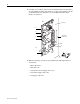
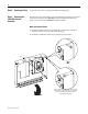
❐ Step 4: Install Voltage Feedback circuit board
❐ Step 5: Install 700S Phase II Main Control assembly
❐ Step 6: Install High Power Fiber Optic Interface circuit board
❐ Step 7: Install 24V Common Mode Filter circuit board
❐ Step 8: Connect I/O and Communications
❐ Step 9: Document change
Step 1: Removing Power
from the Drive
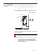
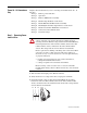
1. Turn off and lock out input power. Wait five minutes.
2. Verify that there is no voltage at the drive’s input power terminals.
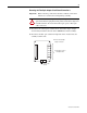
3. Check the DC bus voltage at the Power Terminal Block by measuring
between the +DC and -DC terminals, between the +DC terminal and the
chassis, and between the -DC terminal and the chassis. The voltage must be
zero for all three measurements.
!
ATTENTION: To avoid an electric shock hazard, verify that the
voltage on the bus capacitors has discharged completely before
servicing. Check the DC bus voltage at the Power Terminal Block by
measuring between the +DC and -DC terminals, between the +DC
terminal and the chassis, and between the -DC terminal and the
chassis. The voltage must be zero for all three measurements.
Remove power before making or breaking cable connections. When
you remove or insert a cable connector with power applied, an
electrical arc may occur. An electrical arc can cause personal injury
or property damage by:
• sending an erroneous signal to your system’s field devices,
causing unintended machine motion
• causing an explosion in a hazardous environment
Electrical arcing causes excessive wear to contacts on both the
module and its mating connector. Worn contacts may create electrical
resistance.
L1 L2 L3
O
I