
Manual

Publication 20C-IN001D-EN-P
14
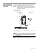
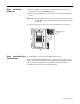
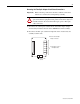
4. Carefully connect ribbon cable from P1 on the Main Control circuit board to
J2 on the High Power Fiber Optic Interface circuit board and ribbon cable P2
on the Main Control circuit board to J1 on the High Power Fiber Optic
Interface circuit board.
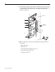
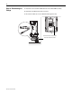
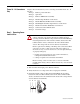
5. Make the following connections on the High Power Fiber Optic Interface
circuit board:
– LED cable to J16
– DPI cable to J4
– 24V Auxiliary Power Supply cable to J15
– Chassis Fan Supply cable to J18
– 24V Supply cable to J5
Screws (5)
Fiber-Optic
Sockets (1 - 9)
J2
J1
J16
J4
J15
J18
J5
=