PowerFlex® 700H to 700S Phase II Control Conversion - Frames 9…14 Installation Instructions ! ! ATTENTION: To avoid an electric shock hazard, ensure that all power to the drive has been removed before performing the following. ATTENTION: To avoid an electric shock hazard, verify that the voltage on the bus capacitors has discharged completely before servicing.
What This Kit Includes • • • • • • • • • • Tools That You Need • Phillips® screwdriver • POZIDRIV® screwdriver • Torx Head screwdriver Phase II control assembly mounting plate, bracket and hardware 40 conductor ribbon cable 30 conductor ribbon cable Status cable 10 conductor ribbon cable for frame 9 drives 10 conductor ribbon cable for frame 10…14 drives Power Interface circuit board and hardware Voltage Feedback circuit board and hardware Phase II control cassette (required, ordered separately) 24V
Step 1: Removing Power from the Drive ! ATTENTION: To avoid an electric shock hazard, verify that the voltage on the bus capacitors has discharged completely before servicing. Check the DC bus voltage at the Power Terminal Block by measuring between the +DC and -DC terminals, between the +DC terminal and the chassis, and between the -DC terminal and the chassis. The voltage must be zero for all three measurements. Remove power before making or breaking cable connections.
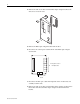
Step 2: Removing the Drive Covers 1. Remove the connection, power and conduit covers as indicated below. Save screws for reuse.
Step 4: Removing the 700H Fiber Optic Adapter Circuit Board The Fiber Optic Adapter circuit board is located behind the 700H control assembly on the opposite side of the control frame. Important: Before removing connections and wires, mark the connections and wires to avoid incorrect wiring during assembly. 1. If removing a control frame from a DC input drive with precharge interlock, disconnect the wiring from terminal strip X50. 2. Remove the eight screws that secure the control frame to the drive.
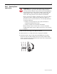
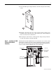
4. Remove the four screws that secure the Fiber Optic Adapter bracket to the drive. Save screws for reuse. 5. Remove the Fiber Optic Adapter bracket from the drive. 6. Disconnect the control power cable from X2 of the Fiber Optic Adapter circuit board. 7 6 5 4 3 H1 through H7 sockets for Fiber-Optic Cables 2 1 X2 Connects to 24V dc Power 7. Disconnect the fiber-optic cables from right side of the circuit board, and carefully set them aside. 8.
9. Secure the Fiber Optic Adapter bracket to the drive using the four existing screws. 10.Install the control frame in reverse order of removal, using existing screws. Carefully route the 24V DC power cable and fiber optic cables through the lower access hole in the control frame. 11.If securing the control frame to a DC input drive with precharge interlock, reconnect the wiring to terminal strip X50.
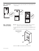
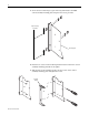
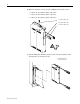
1. Secure the two socket hinges (open end facing downward) to the 700S control assembly mounting plate using the four screws provided. Open end facing downward Mounting plate 2. Insert the two screws for the mounting bracket into the holes in the control assembly mounting plate but do not tighten. 3. Slide the slots of the mounting bracket onto the screws on the control assembly mounting plate and tighten the screws. Mounting bracket 2. 3.
4. Secure the two hinge pins (pins facing upward) to the control frame using the four screws provided. Pin end facing upward Control Frame 5. Slide the 700S control assembly mounting plate onto the hinge pins on the control frame.
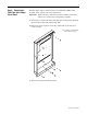
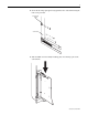
6. Make the following connections on the 700S Phase II Control cassette: – Connect the 10 conductor ribbon cable to P6 – Connect the 40 conductor ribbon cable to P1 – Connect the 30 conductor ribbon cable to P2 10 conductor ribbon cable 40 conductor ribbon cable 30 conductor ribbon cable = 7. Slide the 700S Phase II Main Control Cassette onto the mounting bracket and tighten the two mounting screws.
8. Route the 10 conductor ribbon cable, connected to P6 on the back of the Main Control cassette, under the control frame. 10 conductor ribbon cable routed under control frame Main control mounting plate Note: Main Control cassette not shown for clarity only 9. Swing the Main Control mounting plate in to the frame and tighten the captive screw to secure it to the control frame. Step 6: Installing the Voltage Feedback Circuit Board 1.
2. Secure the Voltage Feedback circuit board to the five standoffs on the control fame using five large standoffs. 3. Secure the clear plastic shield to the mounting plate to the Voltage Feedback circuit board using four screws. J2 = J1 J4 J5 Shield Stand-offs (5) Screws (4) 4. Connect the feedback cables to sockets J1 and J2 of the Voltage Feedback circuit board. ! ATTENTION: Hazard of permanent eye damage exists when using optical transmission equipment.
Step 7: Installing the High Power Fiber Optic Interface Circuit Board 1. Connect the 10 conductor ribbon cable from P6 on the Main Control circuit board to J17 on the High Power Fiber Optic Interface circuit board. Important: Route the 10 conductor ribbon cable, connected to C1 on the back of the Main Control circuit board, under the High Power fiber Optic Interface circuit board. 2. Secure the High Power Fiber Optic Interface circuit board to the control frame using five screws.
4. Carefully connect ribbon cable from P1 on the Main Control circuit board to J2 on the High Power Fiber Optic Interface circuit board and ribbon cable P2 on the Main Control circuit board to J1 on the High Power Fiber Optic Interface circuit board. Screws (5) J2 J1 J16 J4 Fiber-Optic Sockets (1 - 9) J18 J5 J15 = 5.
Step 8: Installing the Chassis Fan 1. Remove the rubber cover from the hole in the upper-right corner of the control frame next to the DPI/HIM assembly. 2. Secure the protective metal grate and the Fan to the control frame using two screws. Important: The fan housing contains an arrow to indicate the direction of the air flow. The arrow should point into the hole above which the fan is mounted. 3. Connect the fan power cable to J18 on the Power Interface circuit board.
Step 10: Documenting the Change 1. Install the new PowerFlex 700S label below the DPI / HIM assembly. 2. Install the new LED Status Indicators label. 3. Record the modification on the Field Installed Option label.
Frame 10…14 Conversions Only Complete these instructions if you are converting a PowerFlex frame 10…14 size drive: ❐ Step 1: Remove power from drive ❐ Step 2: Open drive ❐ Step 3: Remove 700H Control assembly ❐ Step 4: Install Voltage Feedback circuit board ❐ Step 5: Install 700S Phase II Main Control assembly ❐ Step 6: Install High Power Fiber Optic Interface circuit board ❐ Step 7: Install 24V Common Mode Filter circuit board ❐ Step 8: Connect I/O and Communications ❐ Step 9: Document change Step 1:
Step 2: Opening the Drive 1. Open the door of the enclosure that holds the control frame. Step 3: Removing the 700H Main Control Assembly You must move the control frame, remove the Fiber Optic Adapter circuit board connections and remove the 700H Main Control circuit board connections before you can remove the 700H Main Control assembly. Moving the Control Frame 1. Loosen the T8 Torx-head screws that hold the control frame to the drive enclosure (remove screws on early frame 10 drives). 2.
Removing the Fiber Optic Adapter Circuit Board Connections Important: Before removing connections and wires, mark the connections and wires to avoid incorrect wiring during assembly. ! ATTENTION: Hazard of permanent eye damage exists when using optical transmission equipment. This product emits intense light and invisible radiation. Do not look into fiber-optic ports or fiber-optic cable connectors. 3.
Removing the 700H Main Control Circuit Board Connections 5. Unplug the DPI cable and any I/O connections from the 700H Main Control board.
6. Remove the four screws that secure the control bracket to the control frame and remove the control bracket, Main Control assembly and Fiber Optic Adapter circuit board. Remove screws 700H Main Control assembly not shown for clarity only.
7. Remove the screw that secures the two grounding straps to the frame of the enclosure, if present. 8. Re-secure only one of the grounding straps to the control frame with the screw provided, leaving the other grounding strap loose.
Step 4: Installing the Voltage Feedback Circuit Board You must remove the airflow plate and the protective covers before you can install the Voltage Feedback circuit board. Removing the Airflow Plate and Protective Covers 1. Remove the T8 Torx-head screws that secure the airflow plate to the drive. 2. Slide the airflow plate off the enclosure frame.
Removing the Protective Covers on Frames 10…12 Drives Task 1 2 Description Remove the four M5 POZIDRIV screws that secure the top and bottom protective covers to the main front protective cover, then remove the top and bottom protective covers. Remove the four M5 POZIDRIV screws that secure the main front protective cover to the drive, then remove the protective cover.
Installing the Voltage Feedback Circuit Board The Voltage Feedback circuit board is mounted in the locations indicated below.
1. For frame 13 and 14 drives only, remove the four screws that secure the protective cover and insulator for the Voltage Feedback circuit board to the drive and remove the protective cover and insulator.
2. Secure the Voltage Feedback circuit board to the protective frame (and insulator for frame 13 and 14 size drives) using five screws.
3. Carefully connect fiber-optic cable 9 to socket J4 and fiber-optic cable 8 to socket J5 of the Voltage Feedback circuit board. ! ATTENTION: Hazard of permanent eye damage exists when using optical transmission equipment. This product emits intense light and invisible radiation. Do not look into fiber-optic ports or fiber-optic cable connectors. Important: Minimum inside bend radius for fiber-optic cable is 25.4 mm (1 in.).
3. Complete Step 3a or 3b: a. For control frames mounted in a 600 mm (23.6 in.) enclosure, secure the “Z” shaped adapter bracket to the left side of the control frame using three screws. “Z” bracket Control Frame b. For control frames mounted in a 800 mm (31.5 in.) enclosure, secure the “L” shaped adapter bracket to the control frame using three screws.
4. Secure the EMI Shield to the back of the control frame using the four screws provided.
5. Insert the plastic shoulder washers into the holes in the mounting plate and secure the two socket hinges (open end facing downward) and insulation material to the 700S control assembly mounting plate using the four screws provided. Important: The insulation material must be installed between the mounting plate and the socket hinges as shown below. Screws Shoulder washer Mounting plate Insulation material Socket hinge Open end facing downward.
6. Insert the two screws for the mounting bracket into the holes in the control assembly mounting plate but do not tighten. 7. Slide the slots of the mounting bracket onto the screws on the control assembly mounting plate and tighten the screws.
8. Secure the two hinge pins (pins facing upward) to the control frame using the four screws provided. Pin end facing upward Control Frame 9. Insert the two shoulder washers into the stop bracket and install the stop bracket and insulation material with the two screws provided on the control frame. Then, slide the 700S control assembly mounting plate onto the hinge pins on the control frame. Important: The insulation material must be installed between the control frame and the stop bracket.
10.Secure the loose grounding strap to the back of the 700S control assembly mounting plate in one of the two locations illustrated.
11.Make the following connections on the 700S Phase II Control cassette: – Connect the 10 conductor ribbon cable to P6 – Connect the 40 conductor ribbon cable to P1 – Connect the 30 conductor ribbon cable to P2 10 conductor ribbon cable 40 conductor ribbon cable 30 conductor ribbon cable = 12.Slide the Phase II Main Control assembly onto the mounting bracket and tighten the two mounting screws.
Step 6: Installing the High Power Fiber Optic Interface Circuit Board 1. Secure the five standoffs to the back side of the 700S control mounting plate. 2. Secure the High Power Fiber Optic Interface board to the standoffs using five screws. Frame 10, 11 and 13 High Power Fiber Optic Interface board shown. Note: 700S Phase II Control assembly not shown for clarity only Install five screws = 3.
Important: Minimum inside bend radius for fiber-optic cable is 25.4 mm (1 in.). Any bends with a shorter inside radius can permanently damage the fiber-optic cable. Signal attenuation increases with decreased inside bend radii. 5. Carefully connect the ribbon cable from P1 on the Main Control circuit board to J2 on the High Power Fiber Optic Interface circuit board and ribbon cable P2 on the Main Control circuit board to J1 on the High Power Fiber Optic Interface circuit board.
The location of the 24V Common Mode Filter circuit board is different for Step 7: Installing 24V Common Mode Filter Circuit frame 10, 11 and 13 size drives versus frame 12 and 14 size drives. Refer to “Frame 10, 11 & 13 Size Drives” below for frame 10, 11 and 13 size drives Board installation instructions. Refer to “Frame 12 and 14 Size Drives” on page 40 for frame 12 and 14 size drives installation instructions. Frame 10, 11 & 13 Size Drives 1.
3. Connect the twisted pair wires from connector J1 on the 24V Common Mode Filter board to connector J5 on the High Power Fiber Optic Interface board. 4. Connect the 24V power supply cable from connector J8 on the Voltage Feedback board to connector J5 on the 24V Common Mode Filter board. J5 J5 J1 24V Supply cable to J8 on Voltage Feedback circuit board 5. Continue with Step 8 “Connecting I/O and Communications” on page page 40.
Frame 12 and 14 Size Drives 1. Secure the four standoffs to the front of the EMI Shield. 2. Secure the 24V Common Mode Filter circuit board to the four standoffs on the EMI Shield using the four screws provided. 3. Connect the 24V Supply cable from connector J8 on the Voltage Feedback board to connector J5 on the Common Mode Filter board. 4. Connect the twisted pair wires from connector J1 on the Common Mode Filter board to connector J5 on the High Power Star Interface board.
Step 9: Documenting the Change 1. Install the new PowerFlex 700S label below the DPI / HIM assembly. 2. Install the new LED Status Indicators label. 3. Record the modification on the Field Installed Option label.
Related Documentation Allen-Bradley publications are available on the internet at www.rockwellautomation.com/literature.