
Owner manual

PowerFlex® 700S and 700H Frame 14 Replacement Power Structures 7
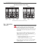
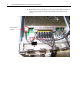
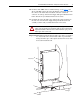
9. Disconnect the cable to the cooling fan, mounted on the ASIC assembly
cover, from connector X1 on the ASIC board and remove the ASIC
assembly cover from each power structure.
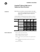
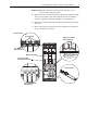
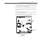
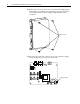
10. Disconnect the fiber optic cables (H1 - H7) from each ASIC board.
11. Disconnect the cable from connector H903 on each ASIC Feedback
board.
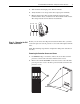
12. For drives with 700H control, disconnect the +24V supply cable from
connector X10 on ASIC board #1.
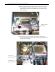
13. For drives with DC input, disconnect the external precharge circuitry
from connectors X9 and X15 from each ASIC board.
H11H12H13
H8
H9H10
X9
X15
X3X4X5
H4H5H6 H1H2H3
H7
X2
X10
X1
Disconnect fiber optic
cables (H1 - H7)
DC precharge
connections
Disconnect
cables