Installation Instructions PowerFlex® 700S and 700H Frame 14 Replacement Power Structures Introduction Important: The Power Modules on PowerFlex 700S Phase II and 700H frame 14 drives are matched at the factory and cannot be paired with any other Power Modules. Therefore, when a Power Module fails, you must replace both power structures on a frame 14 drive. Use this document to install replacement power structures on a frame 14 drive.
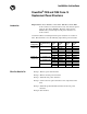
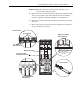
PowerFlex® 700S and 700H Frame 14 Replacement Power Structures Power Structure Locations in Frame 14 Drives Above 1500A Drive Rectifying Structure Power Structure 1500A Drive Power Structure Rectifying Structure Rectifying Structure Power Structure Power Structure Note: Shown with doors and control frames removed for clarity only.
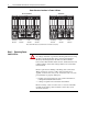
PowerFlex® 700S and 700H Frame 14 Replacement Power Structures 3 1. Turn off and lock out input power. Wait five minutes. 2. Verify that there is no voltage at the drive’s input power terminals. 3. Measure between the +DC and -DC terminals, between the +DC terminal and the chassis, and between the -DC terminal and the chassis. The voltage must be zero for all three measurements.
PowerFlex® 700S and 700H Frame 14 Replacement Power Structures Removing the Air Flow Plates 3. Remove the four T8 Torx-head screws that secure each airflow plate to the drive. 4. Slide each airflow plate off of the drive.
PowerFlex® 700S and 700H Frame 14 Replacement Power Structures 5 Important: Mark all connections and wires before removal to avoid incorrect wiring during assembly. 5. Remove the motor connections from the output power terminals on both of the power structures. Note: The terminals are located in different positions, depending on whether du/dt filters are installed or not. 6. Remove the ground connections from the bottom of the power structure enclosures. 7.
PowerFlex® 700S and 700H Frame 14 Replacement Power Structures 8. Remove the four screws that secure the cover to the ASIC assembly on each power structure and remove the -DC bus connection from the cover.
PowerFlex® 700S and 700H Frame 14 Replacement Power Structures 7 9. Disconnect the cable to the cooling fan, mounted on the ASIC assembly cover, from connector X1 on the ASIC board and remove the ASIC assembly cover from each power structure. 10. Disconnect the fiber optic cables (H1 - H7) from each ASIC board. 11. Disconnect the cable from connector H903 on each ASIC Feedback board. 12. For drives with 700H control, disconnect the +24V supply cable from connector X10 on ASIC board #1. 13.
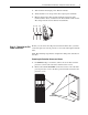
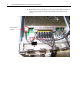
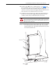
PowerFlex® 700S and 700H Frame 14 Replacement Power Structures 14. Pull the rubber grommet, through which the ASIC board and Power Supply Voltage Feedback board wire bundles are routed, out of the drive frame and secure the wire bundles away from the frame of the power structures. Rubber grommet and wire bundles 15. Disconnect the fan control cables and, for drives with AC input, disconnect the precharge cable from the Rectifying modules located to the left of the ASIC board.
PowerFlex® 700S and 700H Frame 14 Replacement Power Structures 9 16. For drives with 700H control, continue with step 19 on page 11. For drives with 700S control, disconnect the DC bus connection cable from the connector J2 and the motor feedback connection cable from connector J1 at the top of the Power Supply Voltage Feedback board on Power Structure #1 (see illustration below for location). 17.
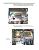
PowerFlex® 700S and 700H Frame 14 Replacement Power Structures 18. Remove the four screws that secure each of the Power Supply Voltage Feedback board assemblies to the fan housing on the power structures and carefully remove the Power Supply Voltage Feedback board assemblies. Remove screws 19. Disconnect the cable from connector J8 on each of the Power Supply Voltage Feedback boards, and set the cable aside.
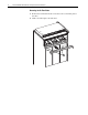
PowerFlex® 700S and 700H Frame 14 Replacement Power Structures 11 20. Remove the two hexagonal screws that secure each power structure to the enclosure frames. Remove screws - one each side of enclosure 21. Follow the instructions in publication PFLEX-IN014…, Installation Instructions - PowerFlex 700S / 700H High Power Maintenance Stand, to install the Maintenance Stand (part number 20-MAINSTND). Remove each power structure by sliding it onto the rails of the Maintenance Stand.
PowerFlex® 700S and 700H Frame 14 Replacement Power Structures Step 3: Installing the New Power Structures Install the new power structures in reverse order of removal. Refer to the publication PFLEX-IN006…, Installation Instructions - PowerFlex 700S and 700H Drives Frames 9 - 14, for tightening torques of power and motor terminations. Step 4: Connecting the Power Structures to Components in the Drive 1.
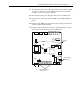
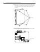
PowerFlex® 700S and 700H Frame 14 Replacement Power Structures 13 Figure 1 ASIC Board and ASIC Feedback Board ASIC Board X5 X4 X3 ASIC Feedback Board H13 H12 H11 H10 H9 H8 H900 H901 X900 H902 X10 H903 X1 X2 H7 H6 H5 H4 H3 H2 H1 X15 X9 Figure 2 Power Supply Voltage Feedback Board J2 J1 J4 J5 J8
PowerFlex® 700S and 700H Frame 14 Replacement Power Structures Figure 3 700S Star Coupler Fiber Interface Board J28 J13 J14 J12 J11 J10 J9 J8 J7 J6 J27 J24 J25 J23 J22 J21 J20 J19 J5
PowerFlex® 700S and 700H Frame 14 Replacement Power Structures Figure 4 700H Star Coupler Fiber Optic Interface Board H8 H7 H6 H5 H4 H3 H2 H1 H18 H17 H16 H15 H14 H13 H12 H11 X2 H23 H22 H21 Figure 5 700S Common Mode Filter Board J1 J5 15
PowerFlex® 700S and 700H Frame 14 Replacement Power Structures PowerFlex 700S Phase II Drives Connections: Figure 6 Connections Between the Power Structure and 700S Phase II Control 6 H903 1 X900 H900 H901 H902 25 26 M 2 3 Sample Pre-Charge Connection Shown in Dashed Lines CR1 1 Fiber Optic 2 4 6 X6 +24V 0EVA DC+ 1 2 3 3 5 7 From DC Bus in Power Circuitry DC- To Rectifying Board X13 To Gate Driver Board X13 To Gate Driver Board X14 To Gate Driver Board X15 To Gate Driver Board H4 To Gate
PowerFlex® 700S and 700H Frame 14 Replacement Power Structures ASIC Board Connections - Power Structure #1 Connect this component : termination point . . .
PowerFlex® 700S and 700H Frame 14 Replacement Power Structures ASIC Feedback Board Connections - Power Structure #1 Connect this component : termination point . . . ASIC Feedback Board: H903 to this component : termination point Star Coupler Fiber Optic Interface Board: J28 ASIC Feedback Board Connections - Power Structure #2 Connect this component : termination point . . .
PowerFlex® 700S and 700H Frame 14 Replacement Power Structures 19 PowerFlex 700H Connections: Figure 7 Connections Between the Power Structure and 700H Control Feedback Board #1 X26 X9 1 25 M 26 2 3 Sample Pre-Charge Connection Shown in Dashed Lines 4 M CR1 X1 2 2 X10 24V Power H1 H2 H3 H4 H5 H6 H7 2 3 4 5 6 7 6 X900 X9 1 M 26 +24V 0EVA 21 22 23 X15 Charge Relay 25 2 3 4 X1 X50 PS #2 1 2 X10 Fiber Optic H1 H2 H3 H4 H5 H6 H7 1 2 3 4 5 6 7 2 1 2 +24VDC GND 5 7 T 6 3 4 1 2
PowerFlex® 700S and 700H Frame 14 Replacement Power Structures ASIC Board Connections - Power Structure #1 Connect this component : termination point . . .
PowerFlex® 700S and 700H Frame 14 Replacement Power Structures 21 Pre-Charge Connections on Drives with DC Input You must connect the ASIC board connectors X9 and X15 to the X50 terminal block for the pre-charge circuit. Refer to publication PFLEX-IN006…, Installation Instructions - PowerFlex 700S and 700H Frame 9-14 Drives, for more information regarding the pre-charge circuit.
PowerFlex® 700S and 700H Frame 14 Replacement Power Structures Step 5: Installing the Product Identification Label on the New Power Structures All frame 14 replacement power structures are shipped from the factory without a product identification label on the drive. If you are installing the power structures in a 700S drive, you should label it with the accompanying PowerFlex 700S label.
PowerFlex® 700S and 700H Frame 14 Replacement Power Structures Reference Materials 23 Allen-Bradley publications are available on the internet at www.rockwellautomation.com/literature.
www.rockwellautomation.com Power, Control and Information Solutions Headquarters Americas: Rockwell Automation, 1201 South Second Street, Milwaukee, WI 53204-2496 USA,Tel: (1) 414.382.2000, Fax: (1) 414.382.