
Owner's manual

PowerFlex® 700S and 700H Frame 13 Replacement Power Structures 19
Step 5: Installing the
Product Identification Label
on New Power Structure
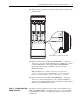
All frame 13 replacement power structures are shipped from the factory
without a product identification label on the drive. If you are installing the
power structures in a 700S drive, you should label it with the accompanying
PowerFlex 700S label. If you are installing the power structures in a 700H
drive, you should label it with the accompanying PowerFlex 700H label.
Step 6: Starting the Drive
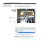
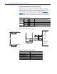
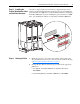
1. Install the protective covers and screens and the air flow plate on the
drive. Installation is in the reverse order of removal as indicated in Step
3: Removing the Old Power Structure
on page 3.
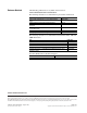
2. Start up the drive. Refer to the Start Up procedures in the appropriate
publication:
– User Manual - PowerFlex 700S Drives with Phase II Control,
20D-UM006…
– Programming Manual - PowerFlex 700H Drives, 20C-PM001…
DC BUS CONDUCT
ORS AND CAP
A
CITORS
OPERA
TE AT HIGH
VOL
TAGE. REMO
VE PO
W
ER
AND W
AIT 5 MINUTES BEFOR
E SER
VICING
DANGER
!
OR