
Owner's manual

12 PowerFlex® 700S and 700H Frame 13 Replacement Power Structures
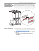
Step 4: Connecting the
Power Structure to
Components in the Drive
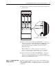
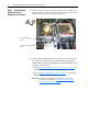
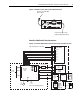
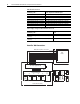
1. For drives with AC input, connect the precharge cable and remove the
jumper from the fan control connector and connect the fan control cable
from the Rectifying modules to the Power Structure.
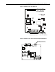
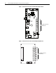
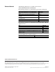
2. Use the tables and illustrations below to make all connections between
the ASIC, Power Supply Voltage Feedback and Fiber Optic Interface
(700S) or Fiber Optic Adapter (700H) and Common Mode Filter circuit
boards for your installation.
– Refer to PowerFlex 700S Phase II Drive Connections:
on page 15 for
a PowerFlex 700S circuit board connection diagram.
– Refer to PowerFlex 700H Connections:
on page 16 for a PowerFlex
700H circuit board connection diagram.
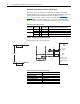
Important:If the drive has DC input, you must also connect the
precharge circuit. Refer to Pre-Charge Connections on
Drives with DC Input on page 18.
=
Connect fan control
cables
Connect Precharge
cables