
User Manual


26 PowerFlex® 700S and 700H Frame 12 Replacement Power Structures
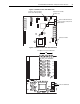
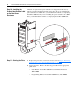
Step 10: Installing the
Product Identification Label
on the New Power
Structures
All frame 12 replacement power structures are shipped form the factory
without a product identification label on the drive. If you are installing the
power structures in a 700S drive, you should label it with the accompanying
PowerFlex 700S label. If you are installing the power structures in a 700H
drive, you should label it with the accompanying PowerFlex 700H label.
Step 11: Starting the Drive
1. Replace the protective covers in the reverse order of Step 2: "Removing
the Protective Covers from the Existing Drive" on page 3.
2. Start up the drive. Refer to the Start Up procedures in the appropriate
publication:
– User Manual - PowerFlex 700S Drives with Phase II Control,
20D-UM006
– Programming Manual - PowerFlex 700H Drives, 20C-PM001
D
C
B
U
S
C
O
N
D
U
C
T
O
R
S
A
N
D
C
A
P
A
C
I
T
O
R
S
O
P
E
R
A
T
E
A
T
H
I
G
H
V
O
L
T
A
G
E
.
R
E
M
O
V
E
P
O
W
E
R
A
N
D
W
A
I
T
5
M
I
N
U
T
E
S
B
E
F
O
R
E
S
E
R
V
I
C
I
N
G
D
A
N
G
E
R
!
DC BUS CONDUCT
ORS AND CAP
A
CITORS
OPERATE AT HIGH VOLTAGE. REMO
VE PO
WER
AND W
AIT 5 MINUTES BEFOR
E SER
VICING
DANGER
!
OR