
User Manual


PowerFlex® 700S and 700H Frame 12 Replacement Power Structures 25
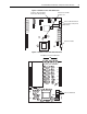
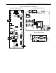
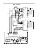
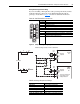
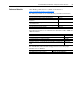
DC Input Precharge Control Wiring
If you are installing a DC input drive with a precharge interlock you must
make the following connections on the X50 terminal block from the
precharge circuit. Refer to Figure 10
below for additional information.
Frame 12 - X50 Terminal Block Connections
Figure 10 Sample Precharge Wiring Diagram
ASIC Board Charge Relay Contact Ratings
X50 Terminal Block Terminal Description
Power Module 1
3 Charge Relay Contact (Jumper to Power Module 2 Terminal 4)
4 Charge Relay Contact
1 Precharge Complete Signal (+24V DC)
2 Precharge Complete Signal (Common)
Power Module 2
3 Charge Relay Contact
4 Charge Relay Contact (Jumper to Power Module 1 Terminal 21)
1 Precharge Complete Signal (+24V DC)
2 Precharge Complete Signal (Common)
1
2
3
4
ASIC
Board
#1
X9
X15
25
26
21
22
23
23
22
X15
26
21
25
Precharge
Complete*
X9
CR1
M
CR1
CR2
M
M
1
2
3
4
PU2
X50
PU1
X50
1
2
3
4
ASIC
Board
#2
Precharge
Complete*
M
*Refer to the “ASIC Board
Charge Relay Contact
Ratings” table below.
External precharge circuitry is shown as dashed lines.
M
F2 R2 CR2
DC+
DC Source
DC-
CR2R1F1
M
Load Resistance load (cos φ = 1)
Rated load 8 A at 250 VAC: 5 A at 30 VDC
Rated carry current 8 A
Max. switching voltage 250 VAC; 30 VDC, (400 VAC)
Max. switching current AC 8 A; DC 5 A
Max. switching power 2,000 VA; 150 W
Failure rate (reference value) 5 VDC 10 mA (for gold plating 0.35 µ min.)