
User Manual

PowerFlex® 700S and 700H Frame 12 Replacement Power Structures 13
Installation on a Grounded B Phase Delta System
If you are installing a drive on a grounded B phase Delta system, you:
• Must move the common mode jumper to the disconnected position -
refer to Move the Common Mode Jumper to the Disconnected
Position on page 14.
• Must insulate terminal X4 on the Rectifier circuit board- refer to Insulate
Terminal X4 on the Rectifier Circuit Board on page 15.
• Must disconnect the small capacitors from the input terminals - refer to
Disconnect the Small Capacitors from the Input Terminals
on page 16.
Note: Refer to Wiring and Grounding Guidelines for Pulse Width
Modulated (PWM) AC Drives - Installation Instructions,
publication DRIVES-IN001…, for additional information on an
ungrounded distribution system or high resistive ground
installation.
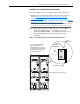
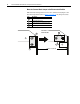
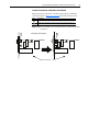
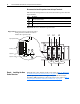
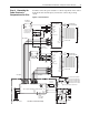
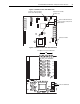
Figure 2 Common Mode Jumper and Rectifier Circuit Board Location
DANGER DANGER
DC BUS CONDUCTORS AND CAPACITORS
OPERATE AT HIGH VOLTAGE. REMOVE POWER
AND WAIT 5 MINUTES BEFORE SERVICING
DANGER DANGER
DC BUS CONDUCTORS AND CAPACITORS
OPERATE AT HIGH VOLTAGE. REMOVE POWER
AND WAIT 5 MINUTES BEFORE SERVICING
Common
Mode jumper
Rectifier Circuit Board
Front View
of Assembly
There is one jumper located on
each Rectifying Module. The
Rectifying Modules are located on
the upper-right side of the right side
power stack of in each enclosure of
the drive’s power structure.
Control Frame not shown for clarity only