
User Manual

PowerFlex® 700S and 700H Frame 11 Replacement Power Structures 15
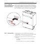
Step 6: Installing the
Product Identification Label
on New Power Structure
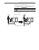
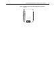
All frame 11 replacement power structures are shipped from the factory
without a product identification label on the drive. If you are installing the
power structure in a 700S drive, you should label it with the accompanying
PowerFlex 700S label. If you are installing the power structure in a 700H
drive, you should label it with the accompanying PowerFlex 700H label.
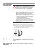
Step 7: Starting the Drive
1. Install the protective covers on the drive. Refer to publication
PFLEX-IN006…, Installation Instructions - PowerFlex 700S and 700H
High Power Drives, for assistance in installing these covers.
2. Start up the drive. Refer to the Start Up procedures in the appropriate
publication:
– User Manual - PowerFlex 700S Drives with Phase II Control,
20D-UM006….
– Programming Manual - PowerFlex 700H Drives, 20C-PM001….
!
DA
NG
ER
Risk of electric shoc
k and death.
Disconnect po
wer
, wait 5 min
utes and
ver
ify DC bus v
oltage before servicing.
Fol
low instructions in manual before use.
Earth g
round required.
!
DANGER
R
isk of electr
ic shoc
k and death.
D
isconnect po
w
er, w
ait 5 m
in
utes and
verify D
C
b
us v
oltage bef
ore ser
vicing.
Fo
llow
instr
uctions in m
an
ua
l b
efore use
.
Earth g
round required
.
OR