
User Manual

14 PowerFlex® 700S and 700H Frame 11 Replacement Power Structures
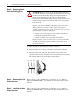
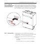
Pre-Charge Connections on Drives with DC Input
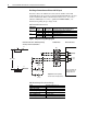
You must connect the ASIC board connectors X9 and X15 to the X50
terminal block for the pre-charge circuit. The X50 terminal block is located
on the Control Frame. Refer to the Installation Instructions - PowerFlex
700S and 700H High Power Drives, publication PFLEX-IN006…, for
information regarding the pre-charge circuit.
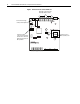
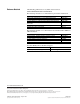
X50 Terminal Block Connections
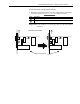
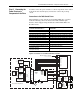
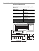
Figure 9 Sample Pre-charge Wiring Diagram
ASIC Board Charge Relay Contact Ratings
ASIC Board
Connector Terminal to X50 Terminal Pre-Charge Circuit Connection Description
X9 25 . . . 1 Pre-charge Complete Signal (+24V DC)
26 . . . 2 Pre-charge Complete Signal (Common)
X15 21 . . . 3 Charge Relay Contact
23 . . . 4 Charge Relay Contact
M
F2 R2 CR2
DC+
DC Source
DC-
CR2R1F1
M
Customer Connections - External precharge
circuitry is shown as dashed lines.
Drive ConnectionsTerminal Block
CR1
Pilot Relay
CR1
M
Main DC Contactor
M
CR2
Precharge
M
Precharge
Complete
1
2
3
4
25
26
21
23
X15
X9
ASIC Board
X50
Charge
Relay*
*Refer to the “ASIC Board
Charge Relay Contact
Ratings” table below.
Important: For DC Input Only.
Do Not Install on AC Input Drives
Load Resistance load (cos φ = 1)
Rated load 8 A at 250 VAC: 5 A at 30 VDC
Rated carry current 8 A
Max. switching voltage 250 VAC; 30 VDC, (400 VAC)
Max. switching current AC 8 A; DC 5 A
Max. switching power 2,000 VA; 150 W
Failure rate (reference value) 5 VDC 10 mA (for gold plating 0.35 µ min.)