
Instruction Manual


16 PowerFlex® 700S and 700H Frame 10 Replacement Power Structures
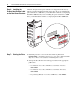
Step 6: Installing the
Product Identification Label
on the New Power Structure
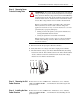
All frame 10 replacement power structures are shipped form the factory
without a product identification label on the drive. If you are installing the
power structure in a 700S drive, you should label it with the accompanying
PowerFlex 700S label. If you are installing the power structure in a 700H
drive, you should label it with the accompanying PowerFlex 700H label.
Step 7: Starting the Drive
1. Install the protective covers on the drive. Refer to publication
PFLEX-IN006…, Installation Instructions - PowerFlex 700S and 700H
High Power Drives, for assistance in installing these covers.
2. Start up the drive. Refer to the Start Up procedures in the appropriate
publication:
– User Manual - PowerFlex 700S Drives with Phase I Control,
20D-UM001
– User Manual - PowerFlex 700S Drives with Phase II Control,
20D-UM006
– Programming Manual - PowerFlex 700H Drives, 20C-PM001.
D
C
B
U
S
C
O
N
D
U
C
T
O
R
S
A
N
D
C
A
P
A
C
I
T
O
R
S
O
P
E
R
A
T
E
A
T
H
I
G
H
V
O
L
T
A
G
E
.
R
E
M
O
V
E
P
O
W
E
R
A
N
D
W
A
I
T
5
M
I
N
U
T
E
S
B
E
F
O
R
E
S
E
R
V
I
C
I
N
G
DAN
GER!
D
C
BU
S
C
O
N
D
U
C
T
O
RS
AN
D C
A
PA
CITO
R
S
OP
ER
ATE
AT HIG
H
VO
L
TAG E
. R
E
M
O
V
E
POW
E
R
A
N
D WA
IT
5 M
IN
UTE
S
BE
FO
R
E SE
R
V
ICIN
G
DANGER
!
OR