
Manual

84 Rockwell Automation Publication PFLEX-IN006E-EN-P - July 2013
Chapter 6 Frame 10 Mechanical Installation
Power Wiring
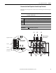
Table 24 - Power Terminal Specifications
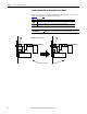
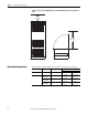
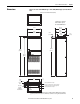
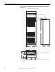
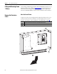
Figure 26 - Power Terminal Locations
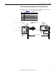
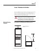
IMPORTANT
Once power wiring has been completed, the protective covers must be re-
installed before energizing the drive. Installation is in reverse order of removal
(see Remove the Protective Covers on page 78
).
No. Name Description Wire Size Range
(1)(2)
Torque Terminal Bolt Size
(3)(4)
Maximum Minimum Recommended
1 Input Power Terminal Block
(3)
L1, L2, L3
Input power 300 mm
2
(600 MCM)
2.1 mm
2
(14 AWG)
40 N•m
(354 lb•in)
M12
2 Output Power Terminal Block
(3)
U/T1, V/T2, W/T3
Motor connections 300 mm
2
(600 MCM)
2.1 mm
2
(14 AWG)
40 N•m
(354 lb•in)
M12
3 SHLD Terminal, PE, Motor Ground
(3)
Terminating point for wiring shields 300 mm
2
(600 MCM)
2.1 mm
2
(14 AWG)
40 N•m
(354 lb•in)
M10
4 DC Bus
(3)
(2 Terminals; DC–, DC+)
DC input or external brake 300 mm
2
(600 MCM)
2.1 mm
2
(14 AWG)
40 N•m
(354 lb•in)
M12
5 Cable Clamp for Shield
(1) Maximum/minimum sizes that the terminal block will accept - these are not recommendations.
(2) Do Not exceed maximum wire size. Parallel connections may be required.
(3) These connections are bus bar type terminations and require the use of lug type connectors.
(4) Apply counter torque to the nut on the other side of terminations when tightening or loosening the terminal bolt in order to avoid damage to the terminal.
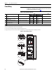
DANGER DANGER
DC BUS CONDUCTORS AND CAPACITORS
OPERATE AT HIGH VOLTAGE. REMOVE POWER
AND WAIT 5 MINUTES BEFORE SERVICING
Cat No.
1234567890-*
1234567890-*
FIELD INSTALLED OPTIONS:FIELD INSTALLED OPTIONS:
DC-
DC+
L1
L2
L3
U/T1
V/T2
W/T3
1
2
3
5
4