
Manual

36 Rockwell Automation Publication PFLEX-IN006E-EN-P - July 2013
Chapter 2 Control Wiring for PowerFlex 700H Drives
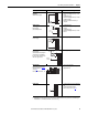
Analog I/O Configuration
See Figure 6 on page 33 for the location of the jumpers indicated in the table
below.
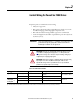
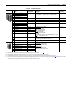
Table 11 - I/O Configuration
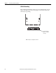
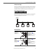
Hardware Enable Circuitry
By default, the user can program a digital input as an Enable input. The status of
this input is interpreted by drive software. If the application requires the drive to be
disabled without software interpretation, a “dedicated” hardware enable
configuration can be utilized. This is done by removing jumper J5 (see table
below) and wiring the enable input to digital input 6. Verify that parameter 366
[Digital In6 Sel] is set to “1-Enable”.
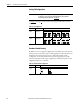
Table 12 - Hardware Enable Configuration
IMPORTANT
Analog I/O must be configured through programming, as well as the jumpers
shown below. See the PowerFlex 700H Adjustable Frequency AC Drive
Programming Manual, publication 20C-PM001
.
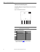
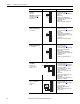
Signal Jumper Setting
Analog
Inputs
J1 (Analog In 1)
J2 (Analog In 2)
0…20 mA 0…10V ±10V
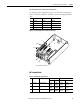
Analog
Outputs
J3 (Analog Out 1)
J4 (Analog Out 2)
0…20 mA 0…10V ±10V
Signal Jumper Setting
Hardware
Enable
J5 Hardware Enable Input Programmable (No Hardware Enable)
CDBA
J1 J2
CDBA
CDBA
J1 J2
CDBA
CDBA
J1 J2
CDBA
CDBA
J3 J4
CDBA
CDBA
J3 J4
CDBA
CDBA
J3 J4
CDBA
BA
J5
BA
J5