
Manual

Rockwell Automation Publication PFLEX-IN006E-EN-P - July 2013 33
Control Wiring for PowerFlex 700H Drives Chapter 2
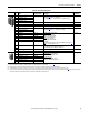
Drive Catalog Numbers for 700H Control I/O Board Options
The following codes are designated in position 15 of the drive catalog string to
indicate the desired combination of 700H I/O option boards supplied with the
drive:
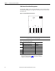
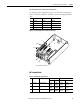
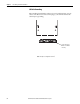
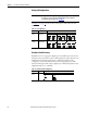
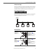
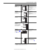
Figure 6 - PowerFlex 700H I/O Terminal Blocks and Jumpers
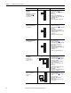
I/O Terminal Blocks
Table 9 - I/O Terminal Block Specifications
Code Board in Slot A Board in Slot B Board in Slot E
A 20C-DA1-A 20C-DO1 20C-DPI1
B 20C-DA1-B 20C-DO1 20C-DPI1
G 20C-DA1-A 20C-DG1 20C-DPI1
N none none 20C-DPI1
No. Name Description Wire Size Range
(1)
(1) Maximum/minimum that the terminal block will accept - these are not recommendations.
Torque
Maximum Minimum Maximum Recommended
1 Analog I/O Analog I/O Signals 2.5 mm
2
(14 AWG)
0.5 mm
2
(22 AWG)
0.2 N•m
1.8 lb•in
0.2 N•m
1.8 lb•in
2 Digital Inputs Digital Input Signals 2.5 mm
2
(14 AWG)
0.5 mm
2
(22 AWG)
0.2 N•m
1.8 lb•in
0.2 N•m
1.8 lb•in
3 Digital Outputs Digital Out Relays 2.5 mm
2
(14 AWG)
0.5 mm
2
(22 AWG)
0.5 N•m
4.5 lb•in
0.5 N•m
4.5 lb•in
I/O Terminal Blocks and Jumpers
J5
J3 & J4
J1 & J2
1
2
3