
Manual

32 Rockwell Automation Publication PFLEX-IN006E-EN-P - July 2013
Chapter 2 Control Wiring for PowerFlex 700H Drives
700H Control Circuit Board Designations
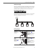
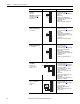
The PowerFlex 700H control circuit board allows for a variety of I/O boards to
be installed depending upon your application. Each option I/O circuit board is
described below.
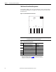
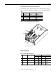
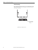
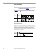
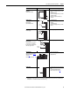
Figure 5 - PowerFlex 700H Control Circuit Board
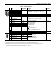
Table 8 - Control Board Slot Designations
IMPORTANT
The boards identified in the table below can only be installed in the designated
slot. Boards and slots are not interchangeable.
Slot Used for Circuit Board . . . Part No.
A 24V DC Digital Input with Analog I/O 20C-DA1-A
115V AC Digital Input with Analog I/O 20C-DA1-B
B 24/115V Digital Output 20C-DO1
24V DC Digital Gate Disable option
(1)
(1) See Appendix E, Instructions for ATEX Approved PowerFlex 700H Drives in Group II Category (2)
Applications with ATEX Approved Motors on page 203
and the PowerFlex 700H AC Drive Safe
Torque Off Option User Manual, publication 20C-UM001
, for more information on installing and
configuring the Gate Disable option board.
20C-DG1
C (Not Used) –
D (Not Used) –
E DPI Option Board 20C-DPI1
Slot
ABCDE