
Manual


26 Rockwell Automation Publication PFLEX-IN006E-EN-P - July 2013
Chapter 1 General Installation Information
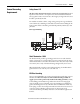
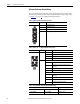
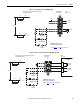
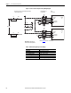
DC Input Precharge Control Wiring
If you are installing a DC input drive with a precharge interlock you must make
the following connections on the X50 terminal block from the precharge circuit.
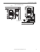
See Figure 1
on page 27 for additional wiring information.
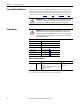
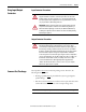
Table 3 - Frame 9 - X50 Terminal Block Connections
Table 4 - Frames 10…14 - X50 Terminal Block Connections
Table 5 - X50 Terminal Block Specifications (All Frame Sizes)
X50 Terminal Block Terminal Description
1Charge Relay Contact
2Charge Relay Contact
5 Precharge Complete Signal (+24V DC)
6 Precharge Complete Signal (Common)
X50 Terminal Block Frame Terminal Precharge Circuit Connection Description
10, 11 & 13 21 Charge Relay Contact
23 Charge Relay Contact
25 Precharge Complete Signal (+24V DC)
26 Precharge Complete Signal (Common)
12 & 14 Power Structure 1
21 Charge Relay Contact
23 Charge Relay Contact (Jumper to Power Structure 2
Terminal 21)
25 Precharge Complete Signal (+24V DC)
26 Precharge Complete Signal (Common)
Power Structure 2
21 Charge Relay Contact (Jumper to Power Structure 1
Terminal 23)
23 Charge Relay Contact
25 Precharge Complete Signal (+24V DC)
26 Precharge Complete Signal (Common)
Wire Size Range
(1)
(1) Maximum/minimum sizes that the terminal block will accept - these are not recommendations.
Torque
Maximum Minimum Recommended
6.0 mm
2
(10 AWG) 1.0 mm
2
(18 AWG) 0.8 N•m (7.0 lb•in)