
Manual


22 Rockwell Automation Publication PFLEX-IN006E-EN-P - July 2013
Chapter 1 General Installation Information
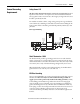
Fuses and Circuit Breakers
Frame 9…14 drives can be installed with either input fuses or an input circuit
breaker. National and local industrial safety regulations and/or electrical codes
may determine additional requirements for these installations. See Fuses and
Circuit Breakers listed in Ta ble 9
on page 176 through Table 16 on page 183.
Power Wiring
Wire Recommendations
ATTENTION: Frame 9…14 PowerFlex drives do not provide branch short circuit
protection. Specifications for recommended fuses to provide protection against
short circuits are provided in the Technical Data publications for the drives.
ATTENTION: National Codes and standards (NEC, VDE, BSI etc.) and local codes
outline provisions for safely installing electrical equipment. Installation must
comply with specifications regarding wire types, conductor sizes, branch circuit
protection and disconnect devices. Failure to do so may result in personal injury
and/or equipment damage.
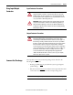
If you are installing... see:
a Frame 9 drive Power Wiring on page 67
a Frame 10 drive Power Wiring on page 84
a Frame 11 drive Power Wiring on page 97
a Frame 12 drive Power Wiring on page 114
a Frame 13 drive Power Wiring on page 130
a Frame 14 drive Power Wiring on page 149
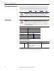
Type Description Min. Insulation Rating
Power
(1)(2)
(1) Control and signal wires should be separated from power wires by at least 0.3 meters (1 foot).
(2) The use of shielded wire for AC input power may not be necessary but is always recommended.
Standard • Four tinned copper conductors with XLPE
insulation.
• Copper braid/aluminum foil combination shield and
tinned copper drain wire.
• PVC jacket.
600V,
75 °C (167 °F)