
Manual


164 Rockwell Automation Publication PFLEX-IN006E-EN-P - July 2013
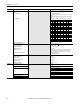
Appendix A Specifications
Category Specification PowerFlex 700H PowerFlex 700S
Protection
Drive 380/400V 480V 500V 600V 690V 380/400V 480V 500V 600V 690V
AC Input Overvoltage Trip: 611V AC 611V AC 611V AC 806V AC 806V AC 675V AC 675V AC 675V AC 889V AC 889V AC
AC Input Undervoltage Trip: 235VAC 235VAC 235VAC 326VAC 326VAC Adjustable
Bus Overvoltage Trip: 911VDC 911V DC 911VDC 1200V DC 1200V DC 911VDC 911VDC 911VDC 1200V DC 1200V DC
Bus Undervoltage Shutoff/Fault: 333VDC 333V DC 333VDC 461VDC 461VDC Adjustable
Nominal Bus Voltage (Full Load): 517VDC 621VDC 645VDC 776VDC 890VDC 540VDC 648VDC 645VDC 810VDC 931V DC
Heat Sink Thermistor: Monitored by microprocessor overtemp trip Monitored by microprocessor overtemp trip
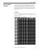
Drive Overcurrent Trip
Software Overcurrent Trip:
Hardware Overcurrent Trip:
Instantaneous Current Limit:
—
360% of rated Heavy Duty current (typical)
—
Calculated value, 105% of motor rated to 200% of drive rated
360% of rated Heavy Duty current (typical)
—
Line transients: up to 6000 volts peak per IEEE C62.41-1991 Up to 6000 volts peak per IEEE C62.41-1991
Control Logic Noise Immunity: Showering arc transients up to 1500V peak Showering arc transients up to 1500V peak
Power Ride-Thru: 15 milliseconds at full load 15 milliseconds at full load
Logic Control Ride-Thru: 0.5 seconds minimum, 2 seconds typical 0.25 seconds, drive not running
Ground Fault Trip: Phase-to-ground on drive output Phase-to-ground on drive output
Short Circuit Trip: Phase-to-phase on drive output Phase-to-phase on drive output
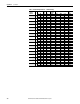
Environment
Altitude: 1000 m (3300 ft.) maximum without derating. Derate the drive by 1% for every
100 m (328 ft.) above 1000 m (3300 ft.).
1000 m (3300 ft.) maximum without derating. Derate the drive by 1% for every
100 m (328 ft.) above 1000 m (3300 ft.).
Maximum Surrounding Air Temperature without
De-rating:
Based on drive rating, refer to Drive Ratings on page 167
. Based on drive rating, refer to Drive Ratings on page 167.
Storage Temperature (all const.): –40 to 60° C (–40 to 140° F) –40 to 70° C (–40 to 158° F)
Atmosphere: Important: Drive must
not be installed in an area where the ambient
atmosphere contains volatile or corrosive gas, vapors or dust. If the drive is not
going to be installed for a period of time, it must be stored in an area where it
will not be exposed to a corrosive atmosphere.
Important: Drive must
not be installed in an area where the ambient
atmosphere contains volatile or corrosive gas, vapors or dust. If the drive is not
going to be installed for a period of time, it must be stored in an area where it
will not be exposed to a corrosive atmosphere.
Relative Humidity: 5 to 95% non-condensing 5 to 95% non-condensing
Shock:
Non-operational 15G peak for 11ms duration (±1.0 ms) 15G peak for 11ms duration (±1.0 ms)
Vibration: 2 mm (0.0787 in.) displacement, 1G peak
EN50178 / EN60068-2-6
2 mm (0.0787 in.) displacement, 1G peak
EN50178 / EN60068-2-6
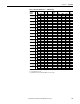
Sound: Frame Sound Level Back- ground
Noise Level
Note: Sound pressure level is
measured at 1 meter. All
devices measured are 400V
IP21 and in power up mode.
Frame Sound Level Back- ground
Noise Level
Note: Sound pressure level is
measured at 1 meter. All
devices measured are 400V
IP21 and in power up mode.
9 78 dba 49 dba 9 78 dba 49 dba
10 77 dba 49 dba 10 77 dba 49 dba
13 76d ba 46 dba 13 76d ba 46 dba
Electrical
AC Input Voltage Tolerance: ±10% ±10%
Frequency Tolerance: 47…63 Hz. 47…63 Hz.
Input Phases: Three-phase input provides full rating for all drives. Single-phase operation
provides 50% of rated current.
Three-phase input provides full rating for all drives. Single-phase operation
provides 50% of rated current.
Displacement Power Factor: 0.98 across entire speed range. 0.98 across entire speed range.
Efficiency: 97.5% at rated amps, nominal line volts. 97.5% at rated amps, nominal line volts.
Maximum Short Circuit Rating: ≤ 200,000 Amps symmetrical. ≤ 200,000 Amps symmetrical.
Actual Short Circuit Rating: Determined by AIC rating of installed fuse/circuit breaker. Determined by AIC rating of installed fuse/circuit breaker.
Maximum Drive to Motor Power Ratio: Recommended not greater than 2:1 ratio. Drive to motor rating cannot exceed a 2:1 ratio.