
Manual

Rockwell Automation Publication PFLEX-IN006E-EN-P - July 2013 159
Frame 14 Mechanical Installation Chapter 10
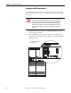
Circuit Breaker DIP Switch Settings
The DIP switches on the circuit breakers are configured to the correct settings at
the factory. However, the settings detailed in Table 32
below should be verified
before charging the circuit breaker motor operators and operating the drive.
Once the settings have been verified, continue with Charging the MCCB Motor
Operators on page 160
.
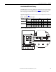
Table 32 - Circuit Breaker DIP Switch Settings
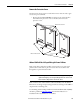
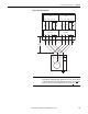
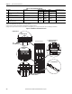
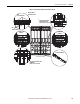
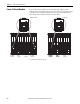
Figure 66 - Circuit Breaker DIP Switches Location
Voltage Class Drive ND
Continuous Amp
Rating
L S/I N
I1 t1 S/I I3 t2 ON/OFF 50% / 100%
400/480V AC 1770 0.76 3 s S 1.5 0.1 s OFF na
2150 0.92 3 s S 1.5 0.1 s OFF na
600/690V AC 1500 0.88 3 s S 1.0 0.1 s OFF na
1900 0.84 3 s S 1.0 0.1 s OFF na
2250 0.96 3 s S 1.5 0.1 s OFF na
OFF
DISCHARGED
SPRING
L
S
I
N
L
N
I1 =
In x (0.4+
t1
S
I
t2
I2=
In x
I3=