
Manual

Rockwell Automation Publication PFLEX-IN006E-EN-P - July 2013 151
Frame 14 Mechanical Installation Chapter 10
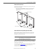
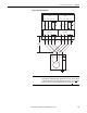
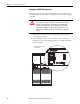
Remove the Protective Covers
You must remove the protective covers from the inverter units in order to gain
access to the power terminals.
• Remove the four M5 POZIDRIV screws that secure each of the three
main and bottom protective covers to the drive, then remove the
protective covers.
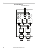
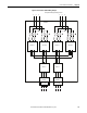
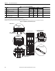
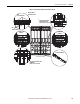
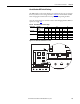
400 and 690 Volt Class AC Input Wiring for Frame 14 Drives
Frame 14 size drives utilize three parallel converter units or two pairs of two
parallel converter units that are pre-connected to line reactors and are fed
through motor operated circuit breakers.
Frame 14 drives can be ordered with or without du/dt filters. The du/dt filter
limits the rate of change of output voltage and the rate of change in the IGBT or
output transistor switching event.
See the Wiring and Grounding Guidelines for Pulse Width Modulated (PWM)
AC Drives, publication DRIVES-IN001
, for minimum inductance on
installations where du/dt filters are not installed.
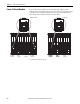
IMPORTANT
Parallel wiring must have the same cable dimensions, type and routing. Non-
symmetrical wiring may cause unequal loading between the converters and
reduce the drive’s ability to deliver current to the motor.
DC BUS CONDUCTORS AND CAPACITORS
OPERATE AT HIGH VOLTAGE. REMOVE POWER
AND WAIT 5 MINUTES BEFORE SERVICING
DANGER
!
DC BUS CONDUCT
ORS AND CAPA
CITORS
OPERATE AT HIGH VOLTAGE. REMO
VE POWER
AND WAIT 5 MINUTES BEFORE SERVICING
DANGER
!
DC BUS CONDUCT
ORS AND CAPACITORS
OPERATE AT HIGH VOLTAGE. REMOVE POWER
AND WAIT 5 MINUTES BEFORE SER
VICING
DANGER
!
Remove screws and covers
Remove screws and covers