
Manual

Rockwell Automation Publication PFLEX-IN006E-EN-P - July 2013 131
Frame 13 Mechanical Installation Chapter 9
Output Power Wiring
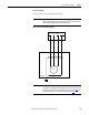
Connect the motor to the output power terminals.
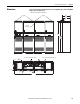
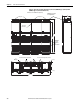
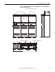
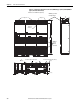
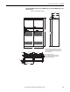
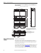
Figure 52 - Frame 13 Motor Wiring Example
IMPORTANT
Parallel wiring must have the same cable dimensions, type and routing. Non-
symmetrical wiring may cause unequal loading between the converters and
reduce the drive’s ability to deliver current to the motor.
IMPORTANT
Once power wiring has been completed, the protective covers must be
installed before energizing the drive. Installation is in reverse order of removal
(see Remove the Protective Covers from the Converter Unit on page 124
and
Remove the Protective Covers from the Inverter Unit on page 128
).
U/T1 V/T2 W/T3 PE
Motor Frame
Motor