
Installation Instructions - Frames 7â¦10 User Manual

68 Rockwell Automation Publication 20B-IN014H-EN-P - June 2013
PowerFlex 700 Adjustable Frequency AC Drive – Frames 7…10
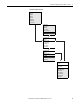
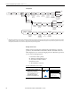
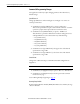
Drive Status Indicators & DPI Port Locations
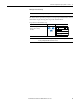
No. Name Color State Description
➊
PWR
(Power)
Green Steady Illuminates when power is applied to the drive.
➋
STS
(Status)
Green Flashing Drive ready, but not running and no faults are present.
Steady Drive running, no faults are present.
Yellow Flashing, Drive Stopped A start inhibit condition exists, the drive cannot be started.
Check parameter 214 [Start Inhibits].
Flashing, Drive Running An intermittent type 1 alarm condition is occurring.
Check parameter 211 [Drive Alarm 1].
Steady, Drive Running A continuous type 1 alarm condition exists.
Check parameter 211 [Drive Alarm 1].
Red Flashing Fault has occurred. Check [Fault x Code] or Fault Queue.
Steady A non-resettable fault has occurred.
➌
PORT Refer to the Communication
Adapter User Manual.
Status of DPI port internal communications (if present).
MOD Status of communications module (when installed).
NET A Status of network (if connected).
NET B Status of secondary network (if connected).
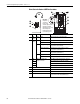
➍ DPI Port 1 HIM connection.
➎ DPI Port 5 Cable connection for communications adapter.
➏ DPI Port 3 or 2 Splitter cable connected to DPI Port 2 provides additional port.
➐ DPI Port 2 Cable connection for handheld and remote options. Located
on side of chassis for Frame 7 IP20, NEMA/UL Type 1.
TB11
TE
25 AMPERES RMS
MAXIMUM
PORT
NET A
NET B
MOD
➊
➋
➌
2
1
o
r3
➍
➐
➏
➊
➋
➌
➎
Important:
Verify metal
ground tab is
bent 90° and is
under the adapter before
tightening screw. After
tightening the screw, verify
that continuity exists
between the head of the
screw and drive ground.