
Installation Instructions - Frames 7â¦10 User Manual

Rockwell Automation Publication 20B-IN014H-EN-P - June 2013 55
PowerFlex 700 Adjustable Frequency AC Drive – Frames 7…10
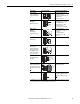
Encoder Specifications
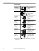
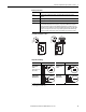
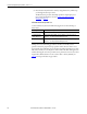
+5/12V Encoder Jumper Location
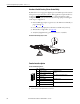
Sample Encoder Wiring
Type: Incremental, dual channel
Supply: 12V, 250 mA. 12V, 10 mA minimum inputs isolated with differential transmitter, 250 kHz
maximum.
Quadrature: 90°, ±27 degrees at 25 degrees C.
Duty Cycle: 50%, +10%
Requirements: Encoders must be line driver type, quadrature (dual channel) or pulse (single channel), 8-15V DC
output (3.5-6V DC when jumpers are in 5V position), single-ended or differential and capable of
supplying a minimum of 10 mA per channel. Maximum input frequency is 250 kHz. The Encoder
Interface Board accepts 12V DC square-wave with a minimum high state voltage of 7.0V DC. With
the jumpers in the 5V position, the encoder accepts a 5V DC square-wave with a minimum high
state voltage of 3.1V DC. In either jumper position, the maximum low state voltage is 0.4V DC.
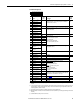
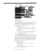
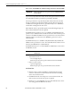
I/O Connection Example I/O Connection Example
Encoder Power –
Internal Drive
Power
Internal (drive) 12V
DC, 250mA
(1)
(1) SHLD connection is on drive chassis.
Encoder Power –
External Power
Source
Encoder Signal –
Single-Ended,
Dual Channel
(2)
(2) Example applies to 20B-ENC-1 only.
Encoder Signal –
Differential,
Dual Channel
J3
5/12V
(20B-ENC-2)
J3
J2
+12V
1
2
3
12 11
21
+5VREF
5/12V
(20B-ENC-1, Series B)
J3
+12V
1
2
3
+5VREF
1
2
3
+5V
+12V
1
2
3
1
2
3
+5V
+12V
1
2
3
+12V
+5V
12 11
21
12 11
21
Output
Cong.
J3
Output
Cong.
J2
Intput
Cong.
Common
+12V DC
(250 mA)
1
2
3
4
5
6
7
8
to SHLD
(1)
+
Common
External
Power
Supply
to
SHLD
(1)
B
B NOT
A NOT
A
Z
Z NOT
to SHLD
(1)
to Power Supply
Common
1
2
3
4
5
6
7
8
to SHLD
(1)
1
2
3
4
5
6
7
8
B
Z
A NOT
B NOT
Z NOT
A