
Installation Instructions - Frames 7â¦10 User Manual

54 Rockwell Automation Publication 20B-IN014H-EN-P - June 2013
PowerFlex 700 Adjustable Frequency AC Drive – Frames 7…10
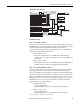
Hardware Enable Circuitry (Vector Control Only)
By default, the user can program a digital input as an Enable input. The status of
this input is interpreted by drive software
. If the application requires the drive to
be disabled without
software interpretation, a “dedicated” hardware enable
configuration can be utilized. This is done by removing a jumper and wiring the
enable input to “Digital In 6.”
1. Remove HIM support plate to gain access to the Main Control Board (see
pages 8
through 11).
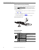
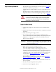
2. Locate & remove Jumper J10 on the Main Control Board (see below).
3. Wire Enable to “Digital In 6” (see page 51
).
4. Verify that [Digital In6 Sel], parameter 366 is set to “1, Enable.”
Hardware Enable Jumper (J10) Location
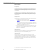
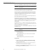
Encoder Interface Option
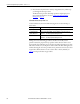
Encoder Terminal Designations
No. Description
8 +12V
(1)
DC Power
(1) Jumper selectable +5/12V is available on 20B-ENC-1 Encoder Boards.
Internal power source
250 mA.
7 +12V
(1)
DC Return (Common)
6 Encoder Z (NOT) Pulse, marker or registration input.
(2)
(2) Z channel can be used as a pulse input while A & B are used for encoder.
5 Encoder Z
4 Encoder B (NOT) Quadrature B input.
3 Encoder B
2 Encoder A (NOT) Single cha nnel or quadrature A input.
1 Encoder A
8
1