
Installation Instructions - Frames 7â¦10 User Manual

52 Rockwell Automation Publication 20B-IN014H-EN-P - June 2013
PowerFlex 700 Adjustable Frequency AC Drive – Frames 7…10
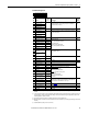
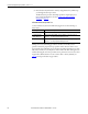
I/O Wiring Examples
Input/Output Connection Example Required Parameter Changes
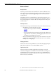
Potentiometer Unipolar
Speed Reference
(1)
10k Ohm Pot. Recommended
(2k Ohm Minimum)
(1) Refer to the Attention statement on page 49 for important bipolar wiring information.
• Adjust Scaling:
Parameters 91/92 and 325/326
• View Results:
Parameter 002
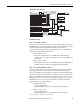
Joystick Bipolar Speed
Reference
(1)
±10V Input
• Set Direction Mode:
Parameter 190 = “1, Bipolar”
• Adjust Scaling:
Parameters 91/92 and 325/326
• View Results:
Parameter 002
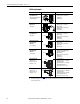
Analog Input Bipolar
Speed Reference
±10V Input
• Set Direction Mode:
Parameter 190 = “1, Bipolar”
• Adjust Scaling:
Parameters 91/92 and 325/326
• View Results:
Parameter 002
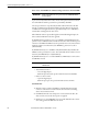
Analog Voltage Input
Unipolar Speed
Reference
0 to +10V Input
• Configure Input with parameter 320
• Adjust Scaling:
Parameters 91/92 and 325/326
• View results:
Parameter 002
Analog Current Input
Unipolar Speed
Reference
0-20 mA Input
• Configure Input for Current:
Parameter 320 and add jumper at
appropriate terminals
• Adjust Scaling:
Parameters 91/92 and 325/326
• View results:
Parameter 002
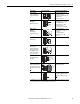
Analog Input, PTC
PTC OT set > 5V
PTC OT cleared < 4V
PTC Short < 0.2V
• Set Fault Config 1:
Parameter 238, bit 7 = “Enabled”
• Set Alarm Config 1:
Parameter 259, bit 11 = “Enabled”
• View Status Drive Alarm 1:
Parameter 211, bit 11 = “True”
HW PTC Input
(2)
PTC OT set > 5V
PTC OT cleared < 4V
PTC Short < 0.2V
(2) A PTC (Positive Temperature Coefficient) device (motor thermistor) embedded in the motor windings, can be monitored by the drive
for motor thermal protection.
• Set Fault Config 1:
Parameter 238, bit 13 = “Enabled”
• Set Alarm Config 1:
Parameter 259, bit 18 = “Enabled”
• View Status: Drive Alarm 1:
Parameter 211, bit 18 = “True”
3
4
5
22
3
5
21
22
3
4
Common
+
3
4
Common
+
3
4
19
20
Common
+
5
3.32k
Ohm
1.8k
PTC
Ferrite
Bead
1
2
22
1.8k
PTC
Ferrite
Bead
10
23