
Installation Instructions - Frames 7â¦10 User Manual


48 Rockwell Automation Publication 20B-IN014H-EN-P - June 2013
PowerFlex 700 Adjustable Frequency AC Drive – Frames 7…10
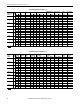
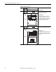
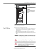
Jumper Settings and Locations
Frame
Voltage
Code
Current
Rating
Factory Default Jumper Settings
Power Source TypeMOV
(1)(2)
7 All All A green/yellow wire connected to a
ground stud on the drive chassis.
Solid Ground
Connect the green/yellow MOV jumper wire to the
ground stud on the drive chassis.
Non-Solid Ground
The green/yellow MOV jumper wire must be
insulated from ground. If necessary, remove the
wire from the stud on the drive chassis. Insulate/
secure the wire to guard against unintentional
contact with the chassis or components.
8…9 All All A green/yellow wire connected
to the PE
bus bar.
Solid Ground
Connect the green/yellow MOV jumper wire to
“PE.”
Non-Solid Ground
Remove the green/yellow MOV jumper wire from
the PE bus bar. Insulate/secure the wire to guard
against unintentional contact with the chassis or
components.
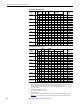
+DC
USE 75
°
COPPER WIRE ONLY
TORQUE LARGE TERMINALS TO 10 N-m (87LB-IN)
-DC PE PE R-L1 T-L3
RISK OF SHOCK
REPLACE AFTER
SERVICING
!
DANGER
U-M1 V-M2 W-M3S-L2
TB11
25 AMPERES RMS
MAXIMUM
ALLEN-BRADLEY
MADE IN U.S.A.
PE
MOV
Ground
Stud
V
W
U
RSTDC-DC+
GND
MOV
(under boards)
PE Bus
Bar