
Installation Instructions - Frames 7â¦10 User Manual

38 Rockwell Automation Publication 20B-IN014H-EN-P - June 2013
PowerFlex 700 Adjustable Frequency AC Drive – Frames 7…10
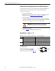
Additional Frame 10 Wiring Requirement for IP00 AC Input Drives
The Inverter and Converter sections of Frame 10 AC Input IP00, NEMA/UL
Type Open drives are shipped separately. Once installed, the following
connections are required.
1. DC Link Choke Wiring
DC link chokes are supplied loose for customer mounting and wiring in
IP00 drives. Refer to DC Link Chokes – Frames 8…10
below.
2. Thermistor Wiring
Thermistor wiring is coiled loose in the Converter section for shipping.
Locate the wire (labeled “To INV”) and route through the enclosure wall.
Connect it to the mating connector above the HIM cradle.
3. Ground the drive chassis
Refer to page 11
for IP00 PE grounding locations.
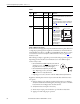
DC Link Chokes – Frames 8…10
DC Link Chokes are supplied with Frame 8…10 AC input drives.
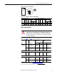
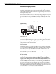
DC Link Choke Wiring
Refer to the diagram and page 34 for
connection information. Drive rating
information can be found on pages 42
…42.
ATTENTION: To avoid possible drive damage, ensure that the
thermistor wiring described above has been properly performed.
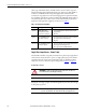
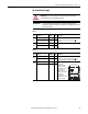
Frame Type DC Link Choke is supplied …
8…9 IP00, NEMA/UL Type Open Mounted and wired
IP20, NEMA/UL Type 1 Mounted and wired
IP00, NEMA/UL Type Open Roll-In Loose without cables (see wiring info below)
10 IP00, NEMA/UL Type Open Loose without cables (see wiring info below)
IP20, NEMA/UL Type 1 Mounted and wired
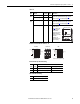
Output to Inverter
Capacitor Bank
Input from
Converter
CNV+
CNV–
INV+
(1) (2)
(4) (3)
INV–
DC–
DC+
to Mounting Foot