
Installation Instructions - Frames 7â¦10 User Manual

34 Rockwell Automation Publication 20B-IN014H-EN-P - June 2013
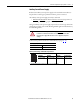
PowerFlex 700 Adjustable Frequency AC Drive – Frames 7…10
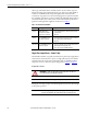
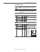
Frame
Terminal Block
AC Input DC Input
7
8…9
10
Terminal Description Notes
DC+/DC-
Top of drive
DC Bus (+)
DC Bus (–)
DC Input/Brake Chopper Connections
DC+/DC-
Power TB
DC Bus (+)
DC Bus (–)
DC Link Choke - wire to:
Bottom of drives (Frames 8…9)
Converter section (Frame 10)
PE PE Ground
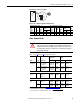
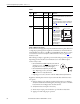
PS+
PS–
AUX (+)
AUX (–)
Auxiliary Control Voltage (see page 39
) for details.
Motor Ground
U
V
W
U (T1)
V (T2)
W (T3)
To Motor
R
S
T
R (L1)
S (L2)
T (L3)
AC Line Input Power
Three-Phase = R, S & T
Single-Phase = R & S Only
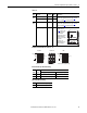
Bus Input Output
DC–DC+ PE PE R-L1 S-L2 T-L3 U-T1 V-T2 W-T3
USE 75° COPPER WIRE ONLY
TORQUE LARGE TERMINALS TO 10 N-m (87 LB-IN)
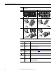
PE
120
DC+ DC-
BUS OUTPUT
U-T1 V-T2 W-T3
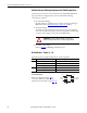
DC Bus/Brake
(top of drive)
DC+
DC
–
* for DC link choke wiring
T
DC
–*
DC+*
S
R
W
U
V
PE
DC+
DC
–
W
U
V
DC Bus/Brake
(top of drive)
PE
DC Bus/Brake
(top of drive)
DC+
DC
–
T
L3
R
L1
W
U
V
PE
(IP20 Versions Only)
R
L1
S
L2
S
L2
T
L3
DC+
DC
–
W
U
V
PE
(IP20 Versions Only)
DC Bus/Brake
(top of drive)