
Installation Instructions - Frames 7â¦10 User Manual

Rockwell Automation Publication 20B-IN014H-EN-P - June 2013 11
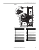
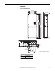
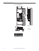
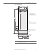
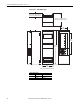
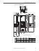
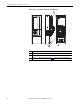
PowerFlex 700 Adjustable Frequency AC Drive – Frames 7…10
Frame 10
AC Input drive is shown. For DC Input drives, reference the left Inverter section.
No. Component No. Component
➊
Motor Terminal Block Inverter Section
➋
PE Ground Converter Section
➌
I/O & Auxiliary Control Voltage - TB11 PE Bus Bar (IP20 Only)
➍
Fan Terminal Block - TB9
(Capacitor Assembly Fan)
DC Link Choke
(AC input only, supplied loose for IP00)
➎
Fan Transformer (IP20 Only) AC Input Terminals (Behind Shield)
➏
Fan Terminal Block - TB10 (Heatsink Fan) PE Connection Point (IP00)
➐
Nameplate DC Bus/Brake Terminals
➑
Main Control Board HIM/Comm Module (Optional)
➒
MOV Jumper Encoder Feedback Board (Optional)
➓
Fan Terminal Block - TB12 (Heatsink Fan)
120
IN1
120
IN2
3
4
5
6
DC+
DANGER
DANGER
TB9
8 AMPERES RMS
MAXIMUM
120
IN1
120
IN2
3
4
5
6
VWU
TB11
PE
25 AMPERES RMS
MAXIMUM
GND
RISK OF SHOCK
REPLACE AFTER
SERVICING
!
DANGER
RISK OF SHOCK
REPLACE AFTER
SERVICING
!
DANGER
RISK OF SHOCK
REPLACE AFTER
SERVICING
!
DANGER
TB10
8 AMPERES RMS
MAXIMUM
DANGE R
120
IN1
120
IN2
3
4
5
6
TB10
8 AMPERES RMS
MAXIMUM
GND
RISK OF SHOCK
REPLACE AFTER
SERVICING
!
DANGER
➋
➍
➎
➒
➐
➏
➑
➌
➓
➊
➐