Installation Instructions PowerFlex 700 Adjustable Frequency AC Drive – Frames 7…10 This document explains the 5 BASIC STEPS needed to install and perform a Basic Start-Up of the PowerFlex 700 AC drive. A Human Interface Module (HIM) is required to perform the Basic Start-Up routine covered in this manual. The information provided is intended for qualified installers only. Additional Resources These documents contain additional information concerning related products from Rockwell Automation.
PowerFlex 700 Adjustable Frequency AC Drive – Frames 7…10 Allen-Bradley Drives Technical Support Use the contacts below for PowerFlex 700 technical support including spare parts information. Documentation in Other Languages Online at… By Email at… By Telephone at… www.ab.com/support/abdrives support@drives.ra.rockwell.com 262-512-8176 User Manuals are available in multiple languages at: http://www.rockwellautomation.com/literature.
PowerFlex 700 Adjustable Frequency AC Drive – Frames 7…10 Table of Contents Catalog Number Explanation . . . . . . . . . . . . . . . . . . . . . . . . . . . . . . . . . . . . . . . . . . . . . 4 Step 1: Read the Precautions and General Information . . . . . . . . . . . . . . . . . . . . . 5 EMC Compliance . . . . . . . . . . . . . . . . . . . . . . . . . . . . . . . . . . . . . . . . . . . . . . . . . . . . . . . 7 Component Locations . . . . . . . . . . . . . . . . . . . . . . . . . . . . . . . . . . .
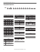
PowerFlex 700 Adjustable Frequency AC Drive – Frames 7…10 Catalog Number Explanation 20B D 325 A 3 A N N N E C 0 b c d e f g h i j k l a a e j Drive HIM Comm Slot Type Code Operator Interface Code Network Type 20B PowerFlex 700 0 Blank Cover C ControlNet (Coax) 3 LCD Display, Full Numeric Keypad D DeviceNet E EtherNet/IP N None b Voltage Ph. Prechg.
PowerFlex 700 Adjustable Frequency AC Drive – Frames 7…10 Step 1: Read the Precautions Qualified Personnel and General Information ATTENTION: Allow only qualified personnel familiar with adjustable frequency AC drives and associated machinery to plan or implement the installation, startup and subsequent maintenance of the system. Failure to comply can result in personal injury and/or equipment damage.
PowerFlex 700 Adjustable Frequency AC Drive – Frames 7…10 Product Safety ATTENTION: An incorrectly applied or installed drive can result in component damage or a reduction in product life. Wiring or application errors, such as, undersizing the motor, incorrect or inadequate AC supply, or excessive ambient temperatures can result in malfunction of the system. ATTENTION: This drive contains ESD (Electrostatic Discharge) sensitive parts and assemblies.
PowerFlex 700 Adjustable Frequency AC Drive – Frames 7…10 EMC Compliance Frame 7…10 drives are CE Certified for use with 400V AC and 480V AC center grounded neutral power supply systems only. The General Grounding Requirements on page 40 must be followed for CE Compliance. It is strongly recommended that the PowerFlex 700 User Manual, publication 20B-UM002 and the Wiring and Grounding Guidelines for Pulse Width Modulated (PWM) AC Drives, publication DRIVES-IN001 be referenced to assure CE EMC compliance.
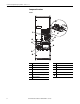
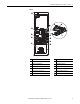
PowerFlex 700 Adjustable Frequency AC Drive – Frames 7…10 Component Locations Frame 7 ➏ DANGER ! ➓ ➑ ! CAUTION HOT SURFACES ➐ ! ➎ ➒ ➋ DANGER RISK OF SHOCK REPLACE AFTER SERVICING ➌ TB11 25 AMPERES RMS MAXIMUM PE ALLEN-BRADLEY MADE IN U.S.A. ➊ ! DANGER RISK OF SHOCK REPLACE AFTER SERVICING +DC -DC PE USE 75° COPPER WIRE ONLY PE R-L1 S-L2 T-L3 U-M1 V-M2 W-M3 TORQUE LARGE TERMINALS TO 10 N-m (87LB-IN) ➍ ➋ 8 No. Component No.
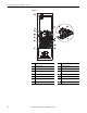
PowerFlex 700 Adjustable Frequency AC Drive – Frames 7…10 Frame 8 ➑ DC+ ➏ ➍ ➐ DANGER ! DANGER RISK OF SHOCK REPLACE AFTER SERVICING TB9 8 AMPERES RMS MAXIMUM ➒ ! DANGER RISK OF SHOCK REPLACE AFTER SERVICING TB11 25 AMPERES RMS MAXIMUM TE ➎ U DC+ W V R S T DC- ➋ ➌ ➊ GND ➓ ➋ No. Component No.
PowerFlex 700 Adjustable Frequency AC Drive – Frames 7…10 Frames 9 ➑ DC+ ➏ ➍ ! ➐ DANGER RISK OF SHOCK REPLACE AFTER SERVICING TB9 8 AMPERES RMS MAXIMUM CAUTION 2 T1 ➒ 4 T2 6 T3 DANGER TB11 25 AMPERES RMS MAXIMUM TE ➎ U DC+ W V R S T DC- GND ➓ 10 ➋ ➌ ➊ ➋ No. Component No.
PowerFlex 700 Adjustable Frequency AC Drive – Frames 7…10 Frame 10 DANGER DC+ ➐ ➑ DANGER DANGER ! DANGER RISK OF SHOCK REPLACE AFTER SERVICING ➒ TB9 8 AMPERES RMS MAXIMUM 120 IN1 ➐ 120 IN2 3 4 5 6 ➍ ! DANGER RISK OF SHOCK REPLACE AFTER SERVICING ➋ ➌ ➊ TB11 25 AMPERES RMS MAXIMUM PE ! ➓ DANGER RISK OF SHOCK REPLACE AFTER SERVICING ! DANGER RISK OF SHOCK REPLACE AFTER SERVICING U V W 120 IN1 120 IN2 3 4 TB10 8 AMPERES RMS MAXIMUM 5 6 GND ➎ TB10 8 AMPERES RMS MAXIMUM 120 I
PowerFlex 700 Adjustable Frequency AC Drive – Frames 7…10 Step 2: Lifting and Mounting the Drive ATTENTION: To guard against possible personal injury and/or equipment damage: • Do Not allow any part of the drive or lifting mechanism to make contact with electrically charged conductors or components. • At no time should a person or their limbs be directly underneath the items being lifted. • Do not subject the load to high rates of acceleration or deceleration.
PowerFlex 700 Adjustable Frequency AC Drive – Frames 7…10 Frames 8, 9 and 10 IP00, NEMA/UL Type Open Approximate Weight Frame 8 – 384 kg (847 lbs.) + 47 kg (103 lbs.) for shipping materials Frame 9 – 401 kg (884 lbs.) + 47 kg (103 lbs.) for shipping materials Frame 10 DC Input 305 kg (672 lbs.) + 47 kg (103 lbs.) for shipping materials AC input 532 kg (1172 lbs.) + 91 kg (200 lbs.
PowerFlex 700 Adjustable Frequency AC Drive – Frames 7…10 Environment Operating Temperatures PowerFlex 700 drives are designed to operate at 0…40 °C ambient. To operate the drive in installations between 41…50 °C, see Table 2 and refer to pages 42 through 44 for exceptions.
PowerFlex 700 Adjustable Frequency AC Drive – Frames 7…10 Dimensions Frame 7 – IP20, NEMA/UL Type 1 514.4 (20.25) 477.3 (18.79) 440.2 (17.33) 406.5 (16.00) 1424.7 (56.01) 1447.8 (57.00) PORT MOD NET A NET B 1498.6 (59.00) Lifting Holes 4 Places 406.7 (16.01) 354.3 (13.95) 261.6 312.4 (10.30) 210.8 (12.30) (8.30) 134.6 (5.30) 38.7 (1.52) 89.5 (3.52) 178.4 (7.02) 58.5 (2.30) 305.4 (12.02) 432.4 (17.02) Dimensions are in millimeters and (inches) Approx. Weight kg (lbs.
PowerFlex 700 Adjustable Frequency AC Drive – Frames 7…10 Frame 7 – IP00, NEMA/UL Type Open 509.3 (20.05) 477.3 (18.79) 440.2 (17.33) 409.3 (16.11) DANGER ! 1419.1 (55.87) ! ! 1447.8 (57.00) CAUTION HOT SURFACES 1498.6 (59.00) DANGER RISK OF SHOCK REPLACE AFTER SERVICING TB11 25 AMPERES RMS MAXIMUM PE ALLEN-BRADLEY MADE IN U.S.A.
PowerFlex 700 Adjustable Frequency AC Drive – Frames 7…10 Frame 7 – Flange Mount Cutout 508.0 (20.00) 5.8 (0.23) Cutout 489.0 (19.25) 127.0 (5.00) 54.1 (2.13) 477.3 (18.79) 1084.1 (42.68) Shading indicates approximate size of drive inside enclosure. 1422.4 (56.00) 1095.8 (43.14) 26 Required 4.3 (0.171) Dia. for 10-32 x 9.7 (0.38) Self-Tap 4.0 (0.159) for 10-32 x 9.7 (0.38) Threaded 127.0 (5.00) * Minimum dimension allowed – More space will improve fan effectiveness and heat dissipation. 75.4 (2.
PowerFlex 700 Adjustable Frequency AC Drive – Frames 7…10 Frames 8 and 9 – IP20, NEMA/UL Type 1 254.6 (10.02) - 20Bx365, 415, 481 381.7 (15.03) - 20Bx535, 600, 730 898.8 (35.39) - 20Bx365, 415, 481 1025.9 (40.39) - 20Bx535, 600, 730 549.7 (21.64) 1466.6 (57.74) 2349.1 (92.49) 757.9 (29.84) Dimensions are in millimeters and (inches) Approx. Weight kg (lbs.
PowerFlex 700 Adjustable Frequency AC Drive – Frames 7…10 Frames 8 and 9 – IP00, NEMA/UL Type Open 757.8 (29.83) 145.3 (5.72) See Table 612.8 (24.13) 241.0 (9.49) 193.3 (7.61) 85.5 (3.37) 549.7 (21.64) 71.3 (2.81) DC+ 1524.0 (60.00) 1466.6 (57.74) DANGER ! DANGER RISK OF SHOCK 2283.7 (89.91) REPLACE AFTER SERVICING TB9 8 AMPERES RMS MAXIMUM ! DANGER RISK OF SHOCK REPLACE AFTER SERVICING TB11 25 AMPERES RMS MAXIMUM TE U DC+ W V R S T DC- GND 463.8 (18.26) 153.0 (6.02) A 603.
PowerFlex 700 Adjustable Frequency AC Drive – Frames 7…10 Frames 8 and 9 – Converting an IP00 Drive for Flange Mounting ➋ DC+ DANGER ! DANGER RISK OF SHOCK REPLACE AFTER SERVICING TB9 8 AMPERES RMS MAXIMUM ! DANGER RISK OF SHOCK REPLACE AFTER SERVICING TB11 25 AMPERES RMS MAXIMUM TE U DC+ W V R S T DC- GND ➊ 20 ➌ No. Component ➊ Remove these IP00 enclosure components. ➋ Drive assembly to be flange mounted.
PowerFlex 700 Adjustable Frequency AC Drive – Frames 7…10 Frames 8 and 9 Roll-In – IP00, NEMA/UL Type Open Dimensions are in millimeters and (inches) DC+ 1612.4 (63.48) DANGER ! DANGER RISK OF SHOCK REPLACE AFTER SERVICING DANGER TB9 8 AMPERES RMS MAXIMUM ! DANGER RISK OF SHOCK REPLACE AFTER SERVICING TB11 25 AMPERES RMS MAXIMUM U DC+ R W V S TE T DC- 648.2 (25.52) 719.8 (28.34) 31.8 (1.24) 45.2 (1.78) A Approx. Weight kg (lbs.) Frame Cat. No.
PowerFlex 700 Adjustable Frequency AC Drive – Frames 7…10 Frames 8 and 9 Roll-In Mounting Considerations Typical Bracket (May require additional anchoring for shipping) Suggested Anchoring Point (M10 Hardware Required) Typical Fan Location (2 Places - 1 Each Door) Alternate Fan Locations Typical Rail Detail 107.4 (4.23) D= 465.8 (18.34) DANGER ! DANGER SHOCK RISK OF AFTER REPLACE SERVICING 58.9 (2.
PowerFlex 700 Adjustable Frequency AC Drive – Frames 7…10 Frames 8 & 9 Flange Mount Cutout 553.3 (21.79) 508.0 (20.00) 22.9 (0.90) 152.4 (6.00) 203.2 (8.00) 152.4 (6.00) 5.6 (0.22) 20 Places 52.1 (2.05) 279.4 (11.00) Dimensions are in millimeters and (inches) 279.4 (11.00) 1471.9 279.4 (57.95) (11.00) 279.4 (11.00) 279.4 (11.00) 603.0 (23.74) This cutout is only needed if recessing the choke IMPORTANT 12.7 (0.50) 463.8 (18.
PowerFlex 700 Adjustable Frequency AC Drive – Frames 7…10 Frame 10 – IP20, NEMA/UL Type 1 AC Input Shown, for DC Input Dimensions use the Inverter (Left) Bay 890.8 (35.07) 2374.0 (93.46) 761.3 (29.97) 507.4 (19.98) 1268.7 (49.95) Dimensions are in millimeters and (inches) Approx. Weight kg (lbs.
PowerFlex 700 Adjustable Frequency AC Drive – Frames 7…10 Frame 10 – IP00, NEMA/UL Type Open AC Input Shown, for DC Input Dimensions use the Inverter (Left) Bay 543.6 (21.40) 591.8 (23.30) 445.8 (17.55) 353.8 (13.93) DANGER DC+ DANGER DANGER ! DANGER RISK OF SHOCK REPLACE AFTER SERVICING TB9 8 AMPERES RMS MAXIMUM 120 IN1 120 IN2 3 2275.8 (89.
PowerFlex 700 Adjustable Frequency AC Drive – Frames 7…10 Frame 10 – Flange Mount Cutout 22.9 (0.90) 508.0 (20.00) 355.6 (14.00) 152.4 (6.00) 22.5 (0.89) 37.7 (1.49) 38.1 (1.50) 152.4 (6.00) 152.4 (6.00) 32.3 (1.27) 39.9 (1.57) 7.6 (0.30) 52.1 (2.05) 279.4 (11.00) hole spacing, 5 places, both sides 381.0 (15.00) 553.3 (21.79) 1588.5 (62.54) 1471.9 (57.95) 254.0 (10.00) hole spacing 5 places, both sides Inverter Converter 22.9 (0.90) 12.7 (0.50) 58.6 (2.31) 66.5 (2.
PowerFlex 700 Adjustable Frequency AC Drive – Frames 7…10 Frame 10 – Flange Mount Cutout Detail 478.8 (18.85) 328.8 (12.94) 178.8(7.04) 95.9 (3.77) 28.7 (1.13) 24.9 (0.98) 558.2 (21.98) 543.3 (21.39) 530.8 (20.90) * * 425.6 (16.75) 414.7 (16.33) 363.7 (14.32) 486.5 (19.15) Fan studs are installed in alternating directions. “ * ” indicates that the stud points-in, all others point-out. * 271.2 (10.68) * 343.0 (13.50) * 199.5 (7.85) * 56.0 (2.
PowerFlex 700 Adjustable Frequency AC Drive – Frames 7…10 DC Link Choke – Frame 8 19.1 (0.75) 16.0 x 9.7 (0.63 x 0.38) 4 Places Dimensions are in millimeters and (inches) 217.9 (8.58) 179.8 228.6 (9.00) Max. (7.08) 370.8 (14.60) 396.2 (15.60) 279.4 (11.00) 203.2 (8.00) 4.7 (0.19) 54.1 (2.13) 54.1 (2.13) 215.9 (8.50) Max. 162.1 (6.38) 4.8 (0.19) 10.2 (0.40) Min. DC Link Choke – Frame 9 342.9 (13.50) 304.8 (12.00) 14.2 (0.56) 188.0 (7.40) 218.4 (8.
PowerFlex 700 Adjustable Frequency AC Drive – Frames 7…10 DC Link Choke – Frame 10 266.7 (10.50) Max 220.9 (8.70) See Detail Top Detail 31.8 (1.25) 280.7 (11.05) 219.7 (8.65) 251.0 (9.90) 12.7 (0.50) 13.5 (0.53) 11.8 (0.47) 7.9 (0.31) 4 PLACES Dimensions are in millimeters and (inches) 244.6 (9.63) 31.8 (1.25) 9.5 (0.38) Dia. 121.8 (4.80) 57.2 (2.25) 12.7 (0.50) 25.4 (1.00) Dia. 2 Places 34.9 (1.38) 305.0 (12.00) Front 222.0 (8.74) 247.7 (9.75) Side 248.0 (9.76) 280.7 (11.
PowerFlex 700 Adjustable Frequency AC Drive – Frames 7…10 Unbalanced, Ungrounded, Resistive or B Phase Grounded Distribution Systems If phase to ground voltage exceeds 125% of normal line to line voltage or the supply system is ungrounded, refer to the Wiring and Grounding Guidelines for Pulse Width Modulated (PWM) AC Drives, publication DRIVES-IN001. ATTENTION: To guard against drive damage, PowerFlex 700 drives contain protective MOVs and common mode capacitors that are referenced to ground.
PowerFlex 700 Adjustable Frequency AC Drive – Frames 7…10 Cable Types Acceptable for 200…600 Volt Installations A variety of cable types are acceptable for drive installations. For many installations, unshielded cable is adequate, provided it can be separated from sensitive circuits. As an approximate guide, allow a spacing of 0.3 meters (1 foot) for every 10 meters (32.8 feet) of length. In all cases, long parallel runs must be avoided.
PowerFlex 700 Adjustable Frequency AC Drive – Frames 7…10 Other types of shielded cable are available, but the selection of these types can limit the allowable cable length. Particularly, some of the newer cables bundle 4 conductors of THHN wire and wrap them tightly with a foil shield. This construction can greatly increase the cable charging current required and reduce the overall drive performance.
PowerFlex 700 Adjustable Frequency AC Drive – Frames 7…10 3 3 1-PH 3-PH LINE TYPE 3 Typical Location - Phase Select Jumper JP1 JP2 JP3 3-PH 1-PH AC Input Precharge Board LINE TYPE SPARE 1 SPARE 2 Table 4 - 380…480 Volt Single-Phase AC Input Ratings 20BD292 20BD325 Amps Drive Catalog Number 0-460 146 20BC292 0-460 162.5 20BC325 Frame Drive Catalog Number 380…400V Single-Phase AC Input Three-Phase Output Hp Rating Input Amps V AC 7 125 237.4 7 125 264.
Frame PowerFlex 700 Adjustable Frequency AC Drive – Frames 7…10 Terminal Block AC Input DC Input 7 DC+ DC– Bus PE 120 PE R-L1 S-L2 T-L3 U-T1 V-T2 W-T3 Input Output USE 75° COPPER WIRE ONLY PE TORQUE LARGE TERMINALS TO 10 N-m (87 LB-IN) DC+ DC- U-T1 BUS 8…9 V-T2 W-T3 OUTPUT DC+ DC+ W DC – W DC –* V DC – DC Bus/Brake (top of drive) T V U DC Bus/Brake (top of drive) S R U DC+* PE PE * for DC link choke wiring 10 DC+ T L3 T L3 S L2 S L2 R L1 DC+ R L1 DC – DC – DC Bus/Br
PowerFlex 700 Adjustable Frequency AC Drive – Frames 7…10 Fan Circuit Power Supply ATTENTION: To avoid a shock hazard, ensure that all power to the drive has been removed before connecting the fan supply. IMPORTANT Some drives utilize a fan transformer to power the internal fan(s). This transformer is sized specifically for the internal fan(s) and must not be used to power other circuitry. Frame 7 Drive Type Enclosure Rating (120VAC) No.
PowerFlex 700 Adjustable Frequency AC Drive – Frames 7…10 Frame 9 Drive Type Enclosure Rating (120VAC) No. of Fans Connect at … DC Input IP00, NEMA/UL Type Open 500 VA 2 IP20, NEMA/UL Type 1 500 VA 2 AC Input IP00, NEMA/UL Type Open 500 VA 2 IP20, NEMA/UL Type 1 500 VA 2 TB9 Requires user supplied 120V AC for cap. bank fan and phase monitor. Blower Terminal Block Three-phase power must be supplied to the Blower TB. See page 10 for TB locations and page 37 for terminal designations.
PowerFlex 700 Adjustable Frequency AC Drive – Frames 7…10 Frame 10 Drive Type Enclosure Rating (120VAC) No. of Fans Connect at … DC Input IP00, NEMA/UL Type Open 1000 VA 2 IP20, NEMA/UL Type 1 1000 VA 2 AC Input IP00, NEMA/UL Type Open 1000 VA 3 TB9, 10 & 12 Requires user supplied 120V AC. See page 11 for TB locations and page 37 for terminal designations. IP20, NEMA/UL Type 1 1000 VA 3 TB9, 10 & 12 A transformer (see page 11) matches the input line voltage to the internal fan voltage.
PowerFlex 700 Adjustable Frequency AC Drive – Frames 7…10 Additional Frame 10 Wiring Requirement for IP00 AC Input Drives The Inverter and Converter sections of Frame 10 AC Input IP00, NEMA/UL Type Open drives are shipped separately. Once installed, the following connections are required. 1. DC Link Choke Wiring DC link chokes are supplied loose for customer mounting and wiring in IP00 drives. Refer to DC Link Chokes – Frames 8…10 below. 2.
PowerFlex 700 Adjustable Frequency AC Drive – Frames 7…10 Auxiliary Control Power Supply If desired, an auxiliary control power supply can be used with certain drives to keep the drive control logic up when the main AC power is removed. An auxiliary control power supply can only be used with: • 400/480 and 600/690 Volt drives with Vector Control (15th position of the catalog number string equals “C,” or “D”).
PowerFlex 700 Adjustable Frequency AC Drive – Frames 7…10 General Grounding Requirements The drive Safety Ground - PE must be connected to system ground. Ground impedance must conform to the requirements of national and local industrial safety regulations and/or electrical codes. The integrity of all ground connections must be periodically checked. For installations within a cabinet, use only a single safety ground point or ground bus bar connected directly to building steel.
PowerFlex 700 Adjustable Frequency AC Drive – Frames 7…10 Motor Overload Protection Class 10 motor overload protection according to NEC article 430 and motor over-temperature protection according to NEC article 430.126 (A)(2). UL 508C File E59272. Drive, Fuse & Circuit Breaker Ratings The PowerFlex 700 can be installed with input fuses or an input circuit breaker. National and local industrial safety regulations and/or electrical codes can determine additional requirements for these installations.
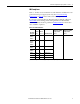
PowerFlex 700 Adjustable Frequency AC Drive – Frames 7…10 400 Volt AC Input Protection Devices (7) 20BC292 20BC325 Max. (5) HD kHz °C Amps Cont.
PowerFlex 700 Adjustable Frequency AC Drive – Frames 7…10 Notes: (1) Minimum protection device size is the lowest rated device that supplies maximum protection without nuisance tripping. (2) Maximum protection device size is the highest rated device that supplies drive protection. For US NEC, minimum size is 125% of motor FLA. Ratings shown are maximum. (3) Circuit Breaker - inverse time breaker. For US NEC, minimum size is 125% of motor FLA. Ratings shown are maximum.
PowerFlex 700 Adjustable Frequency AC Drive – Frames 7…10 Drive Catalog Number 20BP292 Frame 540 Volt DC Input with Precharge kW Rating PWM Freq. Temp. DC Input Ratings ND kHz °C Amps kW Cont. 1 Min. 3 Sec.
PowerFlex 700 Adjustable Frequency AC Drive – Frames 7…10 Output Devices Common mode cores are internal to the drive. For information on output contactors see below. Other devices such as cable terminators and output reactors are discussed in the Wiring and Grounding Guidelines for Pulse Width Modulated (PWM) AC Drives, publication DRIVES-IN001.
PowerFlex 700 Adjustable Frequency AC Drive – Frames 7…10 Disconnecting MOVs The PowerFlex 700 drive contains protective MOVs referenced to ground (see below). To guard against unstable operation and/or damage, the drive must be properly configured as shown in Table 5 on page 47.
PowerFlex 700 Adjustable Frequency AC Drive – Frames 7…10 Table 5 - Recommended Power Jumper Configurations MOV/Input Filter Caps (2) Benefits of Correct Configuration on Power Source Type Solid Ground • AC fed, solidly grounded • DC fed from passive rectifier which has an AC source and solid ground Connected • • • • Non-Solid Ground • AC fed ungrounded • Impedance grounded • High resistive ground • B phase ground • Regenerative unit such as common DC bus supply & brake • DC fed from an active convert
PowerFlex 700 Adjustable Frequency AC Drive – Frames 7…10 7 Voltage Code Current Rating Frame Jumper Settings and Locations Factory Default Jumper Settings MOV (1) (2) Power Source Type All A green/yellow wire connected to a ground stud on the drive chassis. Solid Ground Connect the green/yellow MOV jumper wire to the ground stud on the drive chassis. All TB11 25 AMPERES RMS MAXIMUM Ground Stud PE ALLEN-BRADLEY MADE IN U.S.A.
10 Voltage Code Current Rating Frame PowerFlex 700 Adjustable Frequency AC Drive – Frames 7…10 Factory Default Jumper Settings MOV (1) (2) Power Source Type All A green/yellow wire connected to chassis Solid Ground Connect the green/yellow MOV jumper wire to the chassis. All ! Non-Solid Ground Remove the green/yellow MOV jumper wire from the chassis. Insulate/secure the wire to guard against unintentional contact with the chassis or components.
PowerFlex 700 Adjustable Frequency AC Drive – Frames 7…10 Wire Recommendations Type Signal (1) (2) (3) Wire Type(s) Description Belden 8760/9460 (or equivalent) 0.750 mm2 (18AWG), twisted pair, 100% shield with drain. Belden 8770 (or equivalent) 0.750 mm2 (18AWG), 3 conductor, shielded for remote pot only. Encoder/Pulse I/O <30 m (100 ft.) Combined: Belden 9730 (4) 0.196 mm2 (24AWG), individually shielded Encoder/Pulse I/O 30 to 152 m (100 to 500 ft.) Signal: Belden 9730/9728 (4) 0.
PowerFlex 700 Adjustable Frequency AC Drive – Frames 7…10 I/O Terminal Designations No. Signal 1 Analog In 1 (–) (1) 2 Analog In 1 (+) (1) 3 Analog In 2 (–) (1) 4 Analog In 2 (+) (1) 5 Pot Common – For (+) and (–) 10V pot references. 6 Analog Out 1 (–) (3) 7 Analog Out 1 (+) Bipolar (current output is not bipolar), ±10V/4-20mA, 11 bit & sign, voltage mode - limit current to 5 mA. Current mode - max. load resistance is 400 ohms.
PowerFlex 700 Adjustable Frequency AC Drive – Frames 7…10 I/O Wiring Examples Input/Output Connection Example Potentiometer Unipolar Speed Reference (1) 10k Ohm Pot.
PowerFlex 700 Adjustable Frequency AC Drive – Frames 7…10 Input/Output Connection Example Analog Output ±10V, 0-20 mA Bipolar +10V Unipolar (shown) + Required Parameter Changes • Configure with Parameter 340 • Select Source Value: Parameter 380, [Digital Out1 Sel] • Adjust Scaling: Parameters 343/344 – 2-Wire Control NonReversing(1) 24V DC internal supply • Disable Digital Input:#1: Parameter 361 = “0, Unused” • Set Digital Input #2: Parameter 362 = “7, Run” • Set Direction Mode: Parameter 190 = “0,
PowerFlex 700 Adjustable Frequency AC Drive – Frames 7…10 Hardware Enable Circuitry (Vector Control Only) By default, the user can program a digital input as an Enable input. The status of this input is interpreted by drive software. If the application requires the drive to be disabled without software interpretation, a “dedicated” hardware enable configuration can be utilized. This is done by removing a jumper and wiring the enable input to “Digital In 6.” 1.
PowerFlex 700 Adjustable Frequency AC Drive – Frames 7…10 Encoder Specifications Type: Incremental, dual channel Supply: 12V, 250 mA. 12V, 10 mA minimum inputs isolated with differential transmitter, 250 kHz maximum. Quadrature: 90°, ±27 degrees at 25 degrees C. Duty Cycle: 50%, +10% Requirements: Encoders must be line driver type, quadrature (dual channel) or pulse (single channel), 8-15V DC output (3.
PowerFlex 700 Adjustable Frequency AC Drive – Frames 7…10 Reference Control Auto Speed Sources The drive speed command can be obtained from a number of different sources. The source is determined by drive programming and the condition of the Speed Select digital inputs, Auto/Manual digital inputs or reference select bits of a command word. The default source for a command reference (all speed select inputs are open— the default setting) is the selection programmed in [Speed Ref A Sel].
PowerFlex 700 Adjustable Frequency AC Drive – Frames 7…10 Speed Reference Selection Chart (1) = Default Auto Speed Ref Options Trim Speed Ref A Sel, Parameter 090 Speed Ref B Sel, Parameter 093 Preset Speed 2, Parameter 102 Preset Speed 3, Parameter 103 Preset Speed 4, Parameter 104 Preset Speed 5, Parameter 105 Preset Speed 6, Parameter 106 Preset Speed 7, Parameter 107 DPI Port Ref 1-6, See Parameter 209 [Digital Inx Select]: Speed Sel 3 2 1 0 0 0 0 1 1 1 1 0 0 1 1 0 0 1 1 0 1 0 1 0 1 0 1 PI Excl
PowerFlex 700 Adjustable Frequency AC Drive – Frames 7…10 PLC = Auto, Terminal Block = Manual, with speed reference from the HIM IMPORTANT Requires drive firmware v7.001 or greater and a Series B HIM with firmware v5.004 or greater. A process is run by a PLC when in Auto mode and requires manual control from the terminal block with the speed reference provided by the HIM. The auto speed reference is produced by the PLC and transmitted to the drive through a communications module installed in the drive.
PowerFlex 700 Adjustable Frequency AC Drive – Frames 7…10 Step 5: Start-Up Check List • This check list supports the Basic Start-Up menu option. See page 64 for information on other start-up routines. • A Human Interface Module (HIM) is required to run the Basic Start-Up routine. • The Basic Start-Up routine can modify parameter values for Analog and Digital I/O. Refer to Common I/O Programming Changes on page 70. ATTENTION: Power must be applied to the drive to perform the following start-up procedure.
PowerFlex 700 Adjustable Frequency AC Drive – Frames 7…10 9. Press the Enter key. Follow the menu by using the Enter key which steps you through the Start-Up routine. The Basic Start-Up routine asks simple questions and prompts you to input required information. See also Common I/O Programming Changes on page 70. Information About Start-Up Motor Tests Control schemes vary based on which Start/Jog Source is selected in Step 3. Motor Tests.
PowerFlex 700 Adjustable Frequency AC Drive – Frames 7…10 First Powerup Menu Structure English? Français? Español? Italiano? Deutsch? Português? Nederlands? Not Selected Main Menu: Diagnostics Parameter Device Select Memory Storage Start-Up Preferences PowerFlex 700 Start-Up Startup consists of several steps to configure a drive for basic applications. PowerFlex 700 Start-Up Make a selection 1. SMART 2. Basic 3. Detailed 4. More info PowerFlex 700 Start-Up Complete these steps in order: 1.
PowerFlex 700 Adjustable Frequency AC Drive – Frames 7…10 Supplemental Information DC Input (Common Bus) and Precharge Notes The following notes must be read and understood. Important Application Notes 1. If drives without internal precharge are used (Frame 10 700 Hp only), then: a. precharge capability must be provided in the system to guard against possible damage, and … b.
PowerFlex 700 Adjustable Frequency AC Drive – Frames 7…10 Human Interface Module (HIM) Overview LCD Display Elements Display Description F-> Power Loss Auto 0.0 Hz Direction⎥ Drive Status⎥ Alarm⎥ Auto/Man⎥ Information Commanded or Output Frequency Main Menu: Diagnostics Parameter Device Select Programming / Monitoring / Troubleshooting Human Interface Module (HIM) Key Functions Key Description Esc Exit a menu, cancel a change to a parameter value, or acknowledge a fault/alarm.
PowerFlex 700 Adjustable Frequency AC Drive – Frames 7…10 ALT Functions To use an ALT function, start at the Main Menu and press the ALT key, release it, then press the programming key associated with one of the following functions: ALT Key then ALT Function Function Description Esc S.M.A.R.T. Displays the S.M.A.R.T. screen. This function allows the drive parameter values to be quickly programed by directly accessing the most frequently used drive functions.
PowerFlex 700 Adjustable Frequency AC Drive – Frames 7…10 • Assisted Start Up Three levels of Assisted Start Up (Basic, Detailed and Application) aid the user in commissioning the drive asking simple Yes/No or “Enter Data” questions. The user is guided through the Start Up to reduce the amount of time necessary to get the drive “up and running.
PowerFlex 700 Adjustable Frequency AC Drive – Frames 7…10 Start Up Menu Done / Exit Basic Start-Up Continue Start Over Intro Selection: 1. SMART 2. Basic 3. Detailed 4.
PowerFlex 700 Adjustable Frequency AC Drive – Frames 7…10 Running an Assisted Start Up IMPORTANT This start-up routine requires an LCD HIM. The Assisted start-up routine prompts you to input required information. Access Assisted Start Up by selecting “Start Up” from the Main Menu. To perform an Assisted Start-Up Step Key(s) In the Main Menu, press the Up Arrow or Down Arrow to scroll to “Start Up”. Press Enter. Example LCD Displays F-> Stopped Auto 0.
PowerFlex 700 Adjustable Frequency AC Drive – Frames 7…10 Drive Status Indicators & DPI Port Locations ➊ ➋ ➏ ➍ 1or3 2 ➌ Important: Verify metal ground tab is bent 90° and is under the adapter before tightening screw. After tightening the screw, verify that continuity exists between the head of the screw and drive ground. ➊ ➋ ➌ PORT MOD NET A NET B ➐ TB11 25 AMPERES RMS MAXIMUM TE No. Name Color State Description ➊ PWR (Power) Green Steady Illuminates when power is applied to the drive.
PowerFlex 700 Adjustable Frequency AC Drive – Frames 7…10 AC Precharge Board LED Indications The LEDs are above the “Line Type” jumper shown on page 33. Name Color State Description Power Green Steady Indicates when precharge board power supply is operational Alarm Yellow Flashing [1] [2] [3] [4] [5] [6] [7] Number in “[ ]” indicates flashes and associated alarm (1): Low line voltage (<90%). Very low line voltage (<50%). Low phase (one phase <80% of line voltage).
PowerFlex 700 Adjustable Frequency AC Drive – Frames 7…10 Common I/O Programming Changes Your application needs may require changing parameters from their factory default settings. Speed Reference A Change Speed Reference A from Analog In 2 to Analog In 1 to connect an external potentiometer. 1. Set Parameter 090 [Speed Ref A Sel] to option 1 “Analog In 1” This sets the speed reference input to I/O terminals 1 & 2. For 4…20 mA operation, a jumper must be placed between terminals 17 & 18. 2.
PowerFlex 700 Adjustable Frequency AC Drive – Frames 7…10 Troubleshooting For a complete listing of Faults and Alarms, refer to the PowerFlex 700 User Manual. Fault No. Type(1) Table 6 - Abbreviated Fault Listing Auxiliary Input 2 ➀ Auxiliary input interlock is open. Decel Inhibit 24 ➂ The drive is not following a commanded 1. Verify input voltage is within drive specified Description limits. 2. Verify system ground impedance follows proper grounding techniques. 3.
PowerFlex 700 Adjustable Frequency AC Drive – Frames 7…10 Alarm No. Type(1) Table 7 - Abbreviated Alarm Listing Dig In ConflictA 17 ➁ Digital input functions are in conflict. Combinations marked with a “ ” will cause an alarm. Description Acc2/Dec2 Accel 2 Decel 2 Jog 1/2 Jog Fwd Jog Rev Fwd/Rev Acc2/Dec2 Accel 2 Decel 2 Jog 1/2 Jog Fwd Jog Rev Fwd/Rev Dig In ConflictB 18 ➁ A digital Start input has been configured without a Stop input or other functions are in conflict.
PowerFlex 700 Adjustable Frequency AC Drive – Frames 7…10 Common Symptoms and Corrective Actions Drive does not Start from Start or Run Inputs wired to the terminal block. Cause(s) Indication Corrective Action Drive is Faulted Flashing red status light • • • • • Incorrect input wiring. Refer to the wiring examples starting on page 52. • 2 wire control requires Run, Run Forward, Run Reverse or Jog input. • 3 wire control requires Start and Stop inputs. • Jumper from terminal 25 to 26 is required.
PowerFlex 700 Adjustable Frequency AC Drive – Frames 7…10 Motor and/or drive will not accelerate to commanded speed. Cause(s) Indication Corrective Action Acceleration time is excessive. None Reprogram [Accel Time x]. Excess load or short acceleration times force the drive into current limit, slowing or stopping acceleration. None Check [Drive Status 2], bit 10 to see if the drive is in Current Limit. Remove excess load or reprogram [Accel Time x]. Speed command source or value is not as expected.
PowerFlex 700 Adjustable Frequency AC Drive – Frames 7…10 Manually Clearing Faults Step 1. Press Esc to acknowledge the fault. The fault information is removed so that you can use the Human Interface Module (HIM). 2. Address the condition that caused the fault. 3. The cause must be corrected before the fault can be cleared. 4. After corrective action has been taken, clear the fault by one of these methods: – Press Stop – Cycle drive power – Set parameter 240 [Fault Clear] to “1.
Rockwell Automation Support Rockwell Automation provides technical information on the Web to assist you in using its products. At http://www.rockwellautomation.com/support, you can find technical manuals, technical and application notes, sample code and links to software service packs, and a MySupport feature that you can customize to make the best use of these tools. You can also visit our Knowledgebase at http://www.rockwellautomation.