
Instruction Manual
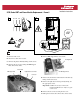

Installation Instructions
Optional
Communications
Module
L2L1T3T2T1 L3
INPUTOUTPUT
USE 75 C
COPPER WIRE
ONLY
TORQUE
52 IN-LB
(6 N-M)
BR2
PS+
PS–
BR1 DC+ DC–
USE 75 C COPPER WIRE ONLY, TORQUE 52 IN-LB (6 N-M)
22-10
AWG
5.3 IN-LB
(0.6 N-M)
WIRE STRIP
2
0V
0V
DC–DC+
3
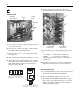
SCR, Brake IGBT and Power Module Replacement - Frame 6
1
L1 L2 L3
O
I
=
A. Remove front covers.
B. Disconnect cables from cassette.
C. Remove the plastic shield by taking out the screws.
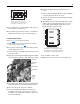
D. Remove the six screws securing the HIM Support
Plate. Disconnect cables.
E. Remove HIM Support Plate and set aside.
F. Remove the junction box on the bottom of the drive by
taking out the four screws.
G. Remove the right-side enclosure panel by taking out
the appropriate screws.
Important: It will be necessary to remove the
terminal end block near “T (L3)” to gain
screw access.
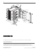
H. Remove the two screws securing the fan cover.
I. Pull-up fan enclosure, disconnect wires and set aside.
HIM Support Plate
Fan Cover
Plastic Shield
Right-Side Enclosure Panel
Precharge Board
HIM Support Plate