
Owner's manual

8 Rockwell Automation Publication 20D-IN010B-EN-P - November 2010
SynchLink™ Board for PowerFlex® 700S Drives with Phase II Control
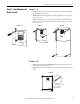
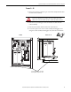
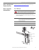
Step 6: Install the New
SynchLink Board
1. Secure the two standoffs to the main control board. Tighten to 0.8… 1.1
N•m (7…10 lb•in).
2. Insert the short pins
of the stacker connector into the mating connector on
the main control board. See the Important statement below.
3. Connect the mating connectors of the new SynchLink board to the long
pins of the stacker connector. See the Important statement below.
4. Secure the SynchLink board to the standoffs using the two screws
provided. Tighten to 0.8… 1.1 N•m (7…10 lb•in).
Step 7: Install the Control
Cassette Inside Cover
Install the control cassette inside cover in the reverse order of removal. Refer to
Step 4: Remove the Inside Cover from the Control Cassette
on page 6.
=
Install two screws
to secure board to
standoffs
Install two standoffs
Install the stacker connector
(see Bottom View below)
Stacker connector
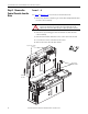
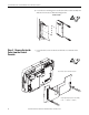
IMPORTANT
The end of the stacker connector with the short pins
must connect to the main control board. The end of
the stacker connector with the long pins must connect
to the SynchLink board.
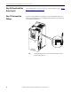
Bottom View
End with short
pins
Main control board
mating connector
SynchLink board
mating connector
End with long pins
Standoff