
Owner's manual


Rockwell Automation Publication 20D-IN010B-EN-P - November 2010 11
SynchLink™ Board for PowerFlex® 700S Drives with Phase II Control
Additional Information
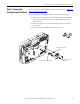
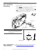
Refer to The SynchLink Design Guide, publication 1756-TD008, when planning
and connecting the SynchLink network.
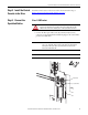
Table 1 - SynchLink Cables and Accessories
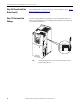
Table 2 - Fiber-Optic Cable Assembly Specifications
Description Cat. No.
3 M Fiber-Optic Link (Qty 2) 1403-CF 003
5 M Fiber-Optic Link (Qty 2) 1403-CF 005
10 M Fiber-Optic Link (Qty 2) 1403-CF 010
500 M Fiber-Optic Bulk 1403-CF BLK
Termination Kit 1403-NTOL
Connector (Qty 10) 1403-N10
Splice Bushing (Qty 5) 1403-N11
Pulling Bullet 1403-N12
Fiber Stripper Tool 1403-N13
SynchLink Fiber-Hub, 1 input, Base 1751-SLBA
SynchLink Fiber-Hub, 4 output, “Star” Splitter 1751-SL4SP
SynchLink Bypass Switch 1751-SLBP/A
Parameter Value
Connecting Cables 200/230 micron HCS (Hard Clad Silica)
Versalink V-System
Lucent Technologies,
Specialty Fibers Technology Division
Maximum Cable Length 300 meters with no more than one splice or one adapter
Minimum Cable Length 1 meter
Minimum inside bend radius 25.4mm (1 in.). Any bends with a shorter inside radius can permanently
damage the fiber-optic cable. Signal attenuation increases with
decreased inside bend radii.
Operating Wavelength 650 nm (Red)
Data Rate 5 Mbps
Maximum Node Count 10 - Daisy Chain
256 - Star Configuration