
User guide

10 Second Encoder Option Card for PowerFlex® 700S Drives with Phase II Control
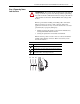
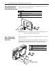
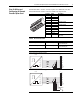
Dip Switch Settings
Dip switch S1 configures the power supply output voltage and the encoder
interface input voltage. Almost all applications require you to set all four
switches on the assembly to either 5V dc or 12V dc.
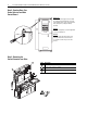
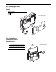
Step 11: Replacing the
Covers and Control
Cassette
The procedure for replacing the covers and control cassette is the reverse of
removing these components. Refer to Step 7: Removing the Embedded
EtherNet/IP Option Card on page 6, Step 5: Removing the Outside Covers
from the Control Cassette on page 5, Step 4: Removing the Inside Cover
from the Control Cassette on page 5 and Step 3: Removing the Control
Cassette from Drive on page 4.
OPEN
1
FRONT - TOP VIEW
SIDE VIEW
UP = OPEN = OFF
DOWN = CLOSED= ON
S1
234
Voltage
Selection
S1-1
(Supply)
S1-2
(A Channel)
S1-3
(B Channel)
S1-4
(Z Channel)
5V dc Closed Closed Closed Closed
12V dc Open Open Open Open