User Manual Safe Torque Off Option for PowerFlex 700S Phase II AC Drives and PowerFlex 700L Liquid-Cooled AC Drives Catalog Number 20D-P2-DG01 Original Instructions
Important User Information Solid state equipment has operational characteristics differing from those of electromechanical equipment. Safety Guidelines for the Application, Installation and Maintenance of Solid State Controls (Publication SGI-1.1 available from your local Rockwell Automation sales office or online at http://www.rockwellautomation.com/ literature/) describes some important differences between solid-state equipment and hard-wired electromechanical devices.
Summary of Changes This manual contains new and updated information. New and Updated Information The following changes apply to this revision of the manual. Change Added “Original Instructions” to the front cover. Updated the Important statement regarding the proper use of the Safe Torque Off option. Updated the information in the Evaluation/Certification by TÜV Rheinland Group table to support frame 5 and 6 and frames 9…14 drives.
Summary of Changes 4 Rockwell Automation Publication 20D-UM007G-EN-P - March 2012
Table of Contents Chapter 1 General Description What Is the DriveGuard Safe Torque Off Option? . . . . . . . . . . . . . . . 7 Safety of Machinery Standards . . . . . . . . . . . . . . . . . . . . . . . . . . . . . . . . . 8 Safety Certifications. . . . . . . . . . . . . . . . . . . . . . . . . . . . . . . . . . . . . . . . . . . 9 Evaluation/Certification by TÜV Rheinland Group . . . . . . . . . . 9 Certifications Online. . . . . . . . . . . . . . . . . . . . . . . . . . . . . . . . . . . . . . .
Table of Contents Chapter 3 Description of Operation DriveGuard Safe Torque Off Operation . . . . . . . . . . . . . . . . . . . . . . . . 29 Connection Examples . . . . . . . . . . . . . . . . . . . . . . . . . . . . . . . . . . . . . . . . 31 Example 1 - PowerFlex 700S Drives, Frames 1…6 Safe Torque Off Connection with Coast-to-Stop Action, Dual Channel. . . . . . . . . . . . . . . . . . . . . . . . . . . . . . . . . . . . . . . . . . . . . . . . . .
Chapter 1 General Description The DriveGuard Safe Torque Off option, when used with other safety components, helps provide protection to meet the requirements for SIL CL2 and Category 3 or PL d class applications. Safety requirements are based on the standards current at the time of certification. The DriveGuard Safe Torque Off option is just one component in a safety control system. Components in the system must be chosen and applied appropriately to achieve the desired level of operator safeguarding.
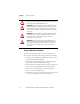
Chapter 1 General Description ATTENTION: Electrical Shock Hazard. Verify that all sources of AC and DC power are de-energized and locked out or tagged out in accordance with the requirements of ANSI/NFPA 70E, Part II. ATTENTION: To avoid an electric shock hazard, verify that the voltage on the bus capacitors has discharged before performing any work on the drive. Measure the DC bus voltage at the +DC and -DC terminals or test points (refer to your drive’s User Manual for locations).
General Description Chapter 1 Safety Certifications The TÜV Rheinland group has approved the DriveGuard Safe Torque Off option for use in safety-related applications where the de-energized state is considered to be the safe state. All of the examples related to I/O included in this manual are based on achieving de-energization as the safe state for typical Machine Safety and Emergency Shutdown (ESD) systems.
Chapter 1 General Description Important Safety Considerations The system user is responsible for: • the set-up, safety rating, and validation of any sensors or actuators connected to the system. • completing a system-level risk assessment and reassessing the system any time a change is made. • certification of the system to the desired safety performance level. • project management and proof testing.
General Description Chapter 1 Safety Category 3 Performance Definition To achieve Safety Category 3 according to EN ISO 13849-1:2008, the safety-related parts have to be designed such that: • the safety-related parts of machine control systems and/or their protective equipment, as well as their components, shall be designed, constructed, selected, assembled, and combined in accordance with relevant standards so that they can withstand expected conditions.
Chapter 1 General Description Performance Level and Safety Integrity Level (SIL) CL2 For safety-related control systems, Performance Level (PL), according to EN ISO 13849-1, and SIL levels, according to IEC 61508 and EN 62061, include a rating of the system’s ability to perform its safety functions. All of the safety-related components of the control system must be included in both a risk assessment and the determination of the achieved levels.
General Description Chapter 1 Functional Proof Tests The functional safety standards require that functional proof tests be performed on the equipment used in the system. Proof tests are performed at user-defined intervals and are dependent upon PFD and PFH values. IMPORTANT Your specific application determines the time frame for the proof test interval.
Chapter 1 General Description Notes: 14 Rockwell Automation Publication 20D-UM007G-EN-P - March 2012
Chapter 2 Installation and Wiring Pre-Installation Instructions Installation must be in accordance with the following steps and must be carried out by competent personnel. The DriveGuard Safe Torque Off option is intended to be part of the safety related control system of a machine.
Chapter 2 Installation and Wiring Option Board Installation PowerFlex 700S Frames 1…6 and PowerFlex 700L Frames 3A and 3B 1. Remove the I/O Control Cassette from the drive. Task Description Open the door of the power structure and disconnect the cables that connect to A the main board. Loosen the screws on the face of the cassette. B Remove the cassette.
Installation and Wiring Chapter 2 PowerFlex 700S Frames 9…14 1. Remove the I/O Control Cassette from the drive. Task Description Open the door of the power structure and carefully disconnect the three cables A that connect to the main board. Loosen the thumb screw that holds the metal flange in place. B C Swing the flange and cassette away from the control frame. D Loosen the screws on the face of the cassette. E Remove the cassette.
Chapter 2 Installation and Wiring PowerFlex 700S, All Frames, and PowerFlex 700L, Frame 3 2. Remove the screws securing the interior cassette cover to gain access to the Main board. 3. Remove the 2-pin shunt jumper from the 16-15 pin position. 16 15 IMPORTANT 18 If the DriveGuard Safe Torque Off option is removed from the drive, this jumper must be reinstalled or the drive will not run.
Installation and Wiring Chapter 2 4. Remove the exterior cassette covers to access the grounding plate.
Chapter 2 Installation and Wiring 5. Install the 16-pin stacker connector. 6. Plug the DriveGuard Safe Torque Off option into the 16-pin connector. 0.8…1.1 N•m (7.0…10.0 lb•in) 7. Install and tighten mounting screws.
Installation and Wiring Chapter 2 8. Install the exterior cassette covers.
Chapter 2 Installation and Wiring 9. Install the inside front cover. 0.8…1.1 N•m (7.0…10.0 lb•in) 10. Reinstall the cassette in the drive. 11. Record the modification on the Field Installed Option label.
Installation and Wiring Chapter 2 PowerFlex 700S Frames 1…6 FIELD INSTALLED OPTIONS Firmware Firmware 20-HIM 28-IO20-COMM20B_-DB1- #: #: Date Date HIM I/O COM Module Internal Dynamic Brake Use marker to note addition of DriveGuard Safe Torque Off option. PowerFlex 700S Frames 9…14 Use marker to note addition of DriveGuard Safe Torque Off option.
Chapter 2 Installation and Wiring PowerFlex 700L Frames 3A and 3B Input Filter Bay Power Module Bay Power Module Bay Door Cutaway FIELD INSTALLED OPTIONS DANGER Power Module Front, Bottom Covers Removed 24 DANGER Firmware Firmware 20-HIM 28-IO20-COMM20B_-DB1- #: #: Date Date HIM I/O COM Module Internal Dynamic Brake Use marker to note addition of DriveGuard Safe Torque Off option.
Installation and Wiring Chapter 2 Wiring Important points to remember about wiring: • Always use tinned copper wire. • Wire with an insulation rating of 600V or greater is recommended. • Control wires should be separated from power wires by at least 0.3 meters (1 foot). • All control wires should be shielded cable with the shield earthed on one end of the cable.
Chapter 2 Installation and Wiring Configure Hardware Enable Ensure that Jumper P22 on the Main Control Board is set to HW Enable (Pins 2 and 4). Jumper P22 4 2 4 2 IMPORTANT 26 3 1 3 1 = HW Enable = No HW Enable In addition to the correct jumper setting, enable circuitry must be connected to I/O Terminals 13 and 16. For wiring examples, refer to the following publications.
Installation and Wiring Chapter 2 Configure Digital Outputs Digital Output 1 and 2 (TB2 Terminals 3, 4, and 5) and Relay Output 3 (TB2 Terminals 6, 7, and 8) can be configured to activate external logic in the event the safety enable diagnostic routine results in an F45 “Enable Health” fault. 1. Set Par 147 [FW Functions En], Bit 14 “Digital Outs” to 1 (True). 2. Set Par 845 [Dig Out1 Sel], Par 850 [Dig Out2 Sel] or Par 855 [Rly Out3 Sel] to option 0 “User Select”. 3.
Chapter 2 Installation and Wiring Verify Operations Test the safety function for proper operation after initial installation of the DriveGuard Safe Torque Off option. Retest the safety function at the intervals determined by the safety analysis described on page 15. Verify that both safety channels are functioning according to Table 4 below.
Chapter 3 Description of Operation DriveGuard Safe Torque Off Operation The DriveGuard Safe Torque Off option disables the drive’s output IGBT’s by disconnecting the gate control power supply (see Figure 1). When used in combination with a second safety channel (the Enable input), the system satisfies the requirements of EN ISO 13849-1, PL d / Category 3 for safe turn off of torque-producing energy at the output of the drive.
Chapter 3 Description of Operation Figure 1 - Drive Safe Torque Off Circuitry AC Line Input Power PowerFlex 700S/700L +24V DC Stop Start Start/Stop Common 24V DC Common Gate Control Power Supply Safe Off Option 3 Safety Channel 4 1 2 Gate Control Circuit Common Safety Channel Enable M 30 Rockwell Automation Publication 20D-UM007G-EN-P - March 2012
Description of Operation Chapter 3 Connection Examples Example 1 - PowerFlex 700S Drives, Frames 1…6 Safe Torque Off Connection with Coast-to-Stop Action, Dual Channel Figure 2 - Stop Category 0 – Coast AC Line Input Power PowerFlex 700S/700L +24V DC Stop Stop +24V DC Gate Start GuardMaster Trojan Start Start/Stop Common 24V DC Common A1 S21 S13 31 13 23 X1 Minotaur MSR9T A2 S22 S14 32 14 24 X2 Gate Control Power Supply Safe Off Option 3 4 1 +24V DC Common 2 Gate Control Circuit Common Enable
Chapter 3 Description of Operation Example 2 - PowerFlex 700S Drives, Frames 9…14 and PowerFlex 700L Drives, Frames 3A and 3B Safe Torque Off Connection with Coast-to-Stop Action, Dual Channel Figure 3 - Stop Category 0 – Coast AC Line Input Power PowerFlex 700S/700L +24V DC GuardMaster Trojan Stop Gate Stop Start Start Start/Stop Common +24V DC A1 S21 S11 S52 S12 S22 37 47 57 13 23 S33 S34 Gate Control Power Supply Minotaur MSR138DP A2 X1 X2 X3 X4 Y39 Y40 38 48 58 +24V DC Common 24V DC Commo
Description of Operation Chapter 3 Application Considerations When the hazard analysis for the overall machine determines the need for external mechanical brakes or other stopping means, the external means shall be activated after the removal of power for Stop Category 0. If the Safe Torque Off option sticks ON, the motor will stop on command due to the enable input. The system cannot be reset when this fault condition exists.
Chapter 3 Description of Operation Operating Principle This is a dual channel system with monitoring of the Safe Torque Off circuit and drive. Opening the guard door will switch the input circuits (S11-S12 & S21-S22) to the Minotaur monitoring safety relay unit. The output circuits (13-14) will issue a Stop command to the drive and cause a controlled deceleration.
Index C O coast-to-stop action, dual channel connection example (frames 1...6), 31 connection example (frames 3A...3B), 32 connection example (frames 9...
Index W wiring option board, 25 36 Rockwell Automation Publication 20D-UM007G-EN-P - March 2012
Index Notes: Rockwell Automation Publication 20D-UM007G-EN-P - March 2012 37
Index Notes: 38 Rockwell Automation Publication 20D-UM007G-EN-P - March 2012
U.S. Allen-Bradley Drives Technical Support Tel: (1) 262.512.8176, Fax: (1) 262.512.2222, Email: support@drives.ra.rockwell.com, Online: www.ab.com/support/abdrives *PN-124644* www.rockwellautomation.com PN-124644 Power, Control and Information Solutions Headquarters Americas: Rockwell Automation, 1201 South Second Street, Milwaukee, WI 53204-2496 USA, Tel: (1) 414.382.2000, Fax: (1) 414.382.