
Manual
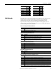
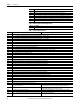
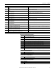

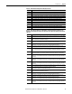
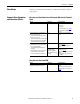
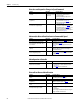
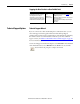

Table Of Contents
- PowerFlex 700H Adjustable Frequency AC Drive Programming Manual
- Summary of Changes
- Table of Contents
- Preface
- 1 - Drive Start-Up
- 2 - Programming and Parameters
- 3 - Troubleshooting
- Drive Status
- Faults and Alarms
- Manually Clear Faults
- Fault and Alarm Descriptions
- Fault Subcodes
- Clear Alarms
- Common Drive Symptoms and Corrective Actions
- Drive does not Start from Start or Run Inputs Wired to the Terminal Block
- Drive does not Start from HIM
- Drive does not Respond to Changes in Speed Command
- Motor and/or Drive will not Accelerate to Commanded Speed
- Motor Operation is Unstable
- Drive will not Reverse Motor Direction
- Stopping the Drive Results in a Decel Inhibit Fault
- Technical Support Options
- A - HIM Overview
- B - Application Notes
- C - History of Changes
- Index
- Back Cover
74 Rockwell Automation Publication 20C-PM001F-EN-P - March 2012
Chapter 3 Troubleshooting
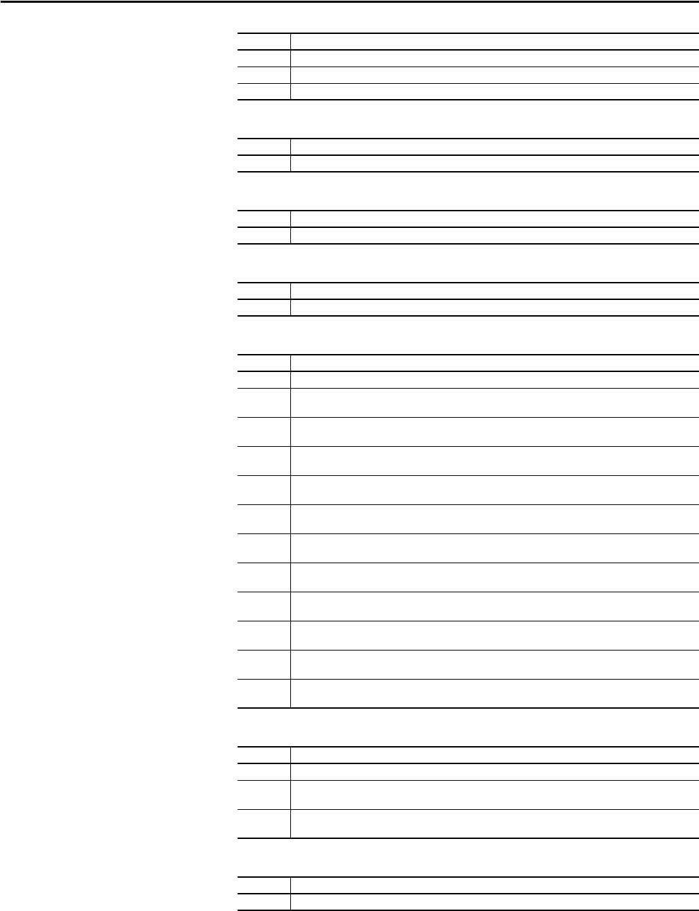
Table 14 - Output Phase Missing Fault (F21) Subcode
Table 15 - Brake Resistor Missing Fault (F28) Subcodes
Table 16 - Microprocessor Watchdog Fault (F30) Subcode
Table 17 - IGBT Temperature Hardware Fault (F31) Subcodes
Table 18 - Fan Cooling Fault (F32) Subcodes
Table 19 - Communication Bus Fault (F34) Subcode
289 One input line phase in power unit 1 is missing.
305 One input line phase in power unit 2 is missing.
529 One input line phase in a regenerative power unit is missing.
Subcode Description
273 There is zero current in one of the output motor phases in the power unit.
Subcode Description
273 No brake resistor has been detected (typically frame 9 drives).
Subcode Description
322 A microprocessor watchdog timeout has occurred on the Control board.
Subcode Description
272, 273 The output current has exceeded the instantaneous current limit in the power unit.
275 The output current has exceeded the instantaneous current limit in the U phase of the power unit (typically
frame 11 and 13 drives).
276 The output current has exceeded the instantaneous current limit in the V phase of the power unit (typically
frame 11 and 13 drives).
277 The output current has exceeded the instantaneous current limit in the W phase of the power unit
(typically frame 11 and 13 drives).
288, 289 The output current has exceeded the instantaneous current limit in power unit 1 (typically frame 12 and 14
drives).
291 The output current has exceeded the instantaneous current limit in the U phase of power unit 1 (typically
frame 14 drives).
292 The output current has exceeded the instantaneous current limit in the V phase of power unit 1 (typically
frame 14 drives).
293 The output current has exceeded the instantaneous current limit in the W phase of power unit 1 (typically
frame 14 drives).
304, 305 The output current has exceeded the instantaneous current limit in power unit 2 (typically frame 12 and 14
drives).
307 The output current has exceeded the instantaneous current limit in the U phase of power unit 2 (typically
frame 14 drives).
308 The output current has exceeded the instantaneous current limit in the V phase of power unit 2 (typically
frame 14 drives).
309 The output current has exceeded the instantaneous current limit in the W phase of power unit 2 (typically
frame 14 drives).
Subcode Description
273 The fan(s) in the power unit does not work according to feedback information.
289 The fans in power unit 1 does not work according to feedback information (typically frame 12 and 14
drives).
305 The fans in power unit 2 does not work according to feedback information (typically frame 12 and 14
drives).
Subcode Description
338 A sent message was not acknowledged.
Subcode Description