
Manual

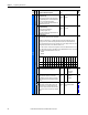


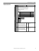
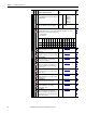

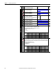
Table Of Contents
- PowerFlex 700H Adjustable Frequency AC Drive Programming Manual
- Summary of Changes
- Table of Contents
- Preface
- 1 - Drive Start-Up
- 2 - Programming and Parameters
- 3 - Troubleshooting
- Drive Status
- Faults and Alarms
- Manually Clear Faults
- Fault and Alarm Descriptions
- Fault Subcodes
- Clear Alarms
- Common Drive Symptoms and Corrective Actions
- Drive does not Start from Start or Run Inputs Wired to the Terminal Block
- Drive does not Start from HIM
- Drive does not Respond to Changes in Speed Command
- Motor and/or Drive will not Accelerate to Commanded Speed
- Motor Operation is Unstable
- Drive will not Reverse Motor Direction
- Stopping the Drive Results in a Decel Inhibit Fault
- Technical Support Options
- A - HIM Overview
- B - Application Notes
- C - History of Changes
- Index
- Back Cover
50 Rockwell Automation Publication 20C-PM001F-EN-P - March 2012
Chapter 2 Programming and Parameters
INPUTS/OUTPUTS
Analog Inputs
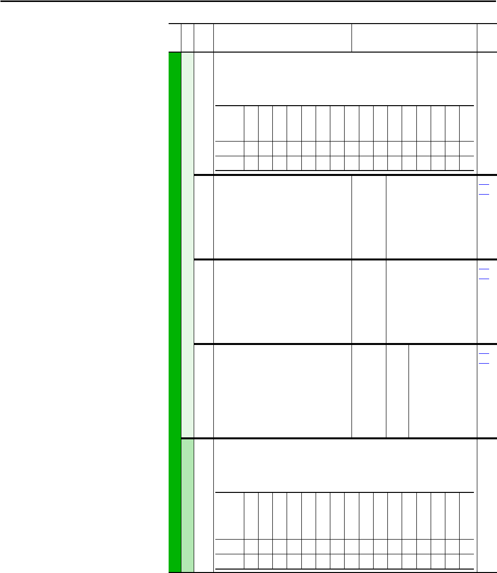
321 [Anlg In Sqr Root]
Enables/disables the square root function for each input.
1 = Enable
0 = Disable
322
325
[Analog In1 Hi]
[Analog In2 Hi]
Sets the highest input value to the analog input x
scaling block.
[Anlg In Config], parameter 320 defines if this
input will be –/+10V or 0-20 mA.
Note: The Min. value was changed from 4.000mA
to 0.000mA for firmware revision 3.001.
Default:
Min/Max:
Units:
10.000 Volt
10.000 Volt
0.000/20.000mA
–/+10.000V
0.000/10.000V
0.001 mA
0.001 Volt
091
092
323
326
[Analog In1 Lo]
[Analog In2 Lo]
Sets the lowest input value to the analog input x
scaling block.
[Anlg In Config], parameter 320 defines if this
input will be –/+10V or 0-20 mA.
Note: The Min. value was changed from 4.000mA
to 0.000mA for firmware revision 3.001.
Default:
Min/Max:
Units:
0.000 Volt
0.000 Volt
0.000/20.000mA
–/+10.000V
0.000/10.000V
0.001 mA
0.001 Volt
091
092
324
327
[Analog In1 Loss]
[Analog In2 Loss]
Selects drive action when an analog signal loss is
detected. Signal loss is defined as an analog
signal less than 1V or 2mA. The signal loss event
ends and normal operation resumes when the
input signal level is greater than or equal to 1.5V
or 3mA.
Default:
Options:
0
0
0
1
2
3
4
5
6
“Disabled”
“Disabled”
“Disabled”
“Fault”
“Hold Input”
“Set Input Lo”
“Set Input Hi”
“Goto Preset1”
“Hold OutFreq”
091
092
Analog Outputs
340 [Anlg Out Config]
Selects the mode for the analog outputs.
1 = Current
0 = Voltage
File
Group
No.
Parameter Name & Description Values
Related
Name
Reserved
Reserved
Reserved
Reserved
Reserved
Reserved
Reserved
Reserved
Reserved
Reserved
Reserved
Reserved
Reserved
Reserved
Analog In 2
Analog In 1
Defaultxxxxxxxxxxxxxx00
Bit 1514131211109876543210
Name
Reserved
Reserved
Reserved
Reserved
Reserved
Reserved
Reserved
Reserved
Reserved
Reserved
Reserved
Reserved
Reserved
Reserved
An2 0=V 1=mA
An1 0=V 1=mA
Defaultxxxxxxxxxxxxxx00
Bit 1514131211109876543210