Programming Manual PowerFlex 700H Adjustable Frequency AC Drive Firmware Revisions 1.xxx ... 6.
Important User Information Solid-state equipment has operational characteristics differing from those of electromechanical equipment. Safety Guidelines for the Application, Installation and Maintenance of Solid State Controls (publication SGI-1.1 available from your local Rockwell Automation® sales office or online at http://www.rockwellautomation.com/literature/) describes some important differences between solid-state equipment and hard-wired electromechanical devices.
Summary of Changes This manual contains new and updated information. Changes throughout this revision are marked by change bars, as shown to the right of this paragraph. New and Updated Information This table contains the changes made to this revision. Topic Page Updated the description for parameter 465 [Fan Control] to indicate that the default value has been changed to 1 “Enabled.” 32 Updated parameter 212 [Drive Alarm 2] to include new bit 8 “Fan Cooling.
Summary of Changes Notes: 4 Rockwell Automation Publication 20C-PM001F-EN-P - March 2012
Table of Contents Preface Who Should Use this Manual . . . . . . . . . . . . . . . . . . . . . . . . . . . . . . . . . . . . . . . 7 What Is Not in this Manual. . . . . . . . . . . . . . . . . . . . . . . . . . . . . . . . . . . . . . . . . 7 Additional Resources . . . . . . . . . . . . . . . . . . . . . . . . . . . . . . . . . . . . . . . . . . . . . . . 8 General Precautions . . . . . . . . . . . . . . . . . . . . . . . . . . . . . . . . . . . . . . . . . . . . . . . .
Table of Contents Appendix B Application Notes External Brake Resistor . . . . . . . . . . . . . . . . . . . . . . . . . . . . . . . . . . . . . . . . . . . 87 Minimum Speed . . . . . . . . . . . . . . . . . . . . . . . . . . . . . . . . . . . . . . . . . . . . . . . . . 87 Motor Control Technology . . . . . . . . . . . . . . . . . . . . . . . . . . . . . . . . . . . . . . . 88 Motor Overload. . . . . . . . . . . . . . . . . . . . . . . . . . . . . . . . . . . . . . . . . . . . . . . . . . 89 Overspeed .
Preface The purpose of this manual is to provide you with the basic information needed to start-up, program and troubleshoot the PowerFlex 700H adjustable frequency AC drive. For information on… See page… Who Should Use this Manual Below What Is Not in this Manual Below Additional Resources 8 General Precautions 8 Who Should Use this Manual This manual is intended for qualified personnel. You must be able to program and operate Adjustable Frequency AC drives and related devices.
Preface Additional Resources These documents contain additional information concerning related products from Rockwell Automation. Resource Description Industrial Automation Wiring and Grounding Guidelines, publication 1770-4.1 Provides general guidelines for installing a Rockwell Automation industrial system.
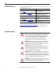
Preface ATTENTION: The sheet metal cover and mounting screws on the ASIC Board located on the power structure are energized at (-) DC bus potential high voltage. Risk of electrical shock, injury, or death exists if someone comes in contact with the assembly. ATTENTION: The “adjust freq” portion of the bus regulator function is extremely useful for preventing nuisance overvoltage faults resulting from aggressive decelerations, overhauling loads, and eccentric loads.
Preface Notes: 10 Rockwell Automation Publication 20C-PM001F-EN-P - March 2012
Chapter 1 Drive Start-Up This chapter describes how you start up the PowerFlex 700H drive. Refer to Appendix A for a brief description of the LCD Human Interface Module (HIM). For Information on… See page… Prepare For Drive Start-Up Below Start-Up the Drive 12 ATTENTION: Power must be applied to the drive to perform the following startup procedure. Some of the voltages present are at incoming line potential.
Chapter 1 Drive Start-Up Apply Power to the Drive ❏ 4. Apply AC power and control voltages to the drive. • If the STS (status) LED is NOT flashing green, refer to Drive Status on page 62 for more information. • If any of the six digital inputs are configured for “Stop – CF” (CF = Clear Fault) or “Enable,” verify that signals are present or reconfigure [Digital Inx Sel].
Drive Start-Up Chapter 1 Running S.M.A.R.T. Start During a Start Up, the majority of applications require changes to only a few parameters. The LCD HIM on a PowerFlex 700H drive offers S.M.A.R.T. start, which displays the most commonly changed parameters. With these parameters, you can set the following functions: S - Start Source and Stop Mode M - Minimum and Maximum Speed A - Accel Time 1 and Decel Time 1 R - Reference Source T - Thermal Motor Overload To run a S.M.A.R.T.
Chapter 1 Drive Start-Up Notes: 14 Rockwell Automation Publication 20C-PM001F-EN-P - March 2012
Chapter 2 Programming and Parameters This chapter provides a complete list and description of the PowerFlex 700H parameters. The parameters can be programmed (viewed/edited) using an LCD Human Interface Module (HIM). As an alternative, programming can also be performed using DriveExplorer™ or DriveExecutive™ software and a personal computer. Refer to HIM Overview on page 81 for a brief description of the LCD HIM.
Chapter 2 Programming and Parameters This table is an example of how each parameter type is presented in this manual. Each numbered column is described in the table following this example. MOTOR . . . Motor Data Column No.
Programming and Parameters How Parameters are Organized Chapter 2 The LCD HIM displays parameters in a File-Group-Parameter or Numbered List view order. To switch display mode, access the Main Menu, press ALT, then Sel while the cursor is on the parameter selection. In addition, using [Param Access Lvl], you can display only the commonly used parameters or all parameters. File-Group-Parameter Order View This view simplifies programming by grouping parameters that are used for similar functions.
Chapter 2 Programming and Parameters File Inputs/Outputs Inputs Group Parameters Analog Inputs Anlg In Config Analog In1 Hi 320 322 Analog In1 Lo Analog In2 Hi 323 325 Analog In2 Lo 326 Analog Outputs Analog Out1, 2 Sel Analog Out1 Hi 342 343 Analog Out1, 2 Lo Analog Out1, 2 Sel 344 345 Analog Out2 Hi Analog Out1, 2 Lo 346 347 Digital Inputs Digital In1 Sel Digital In2 Sel Digital In3 Sel 361 362 363 Digital In4 Sel Digital In5 Sel Digital In6 Sel 364 365 366 20C-DG1 Remove 20C-DG1 S
Programming and Parameters File Utility Utility Communication Group Parameters Direction Config Direction Mode HIM Ref Config Save HIM Ref 192 Man Ref Preload 193 MOP Config Save MOP Ref 194 MOP Rate 195 Drive Memory Param Access Lvl Reset To Defalts Load Frm Usr Set Save To User Set 196 197 198 199 Reset Meters Language Voltage Class Drive Checksum 200 201 202 203 Dyn UserSet Cnfg Dyn UserSet Sel Dyn UserSet Actv 204 205 206 Diagnostics Drive Status 1 Drive Status 2 Drive Alarm 1 D
Parameter Name & Description 001 [Output Freq] Values Default: Related Monitor File No. Programming and Parameters File Group Chapter 2 Read Only Output frequency present at U/T1, V/T2 & W/T3. Min/Max: –/+[Maximum Freq] Units: 0.1 Hz 002 [Commanded Speed] Default: Read Only 32 Value of the active Speed/Frequency Reference. Displayed in Hz or RPM, depending on value of [Speed Units]. 003 [Output Current] 079 Min/Max: –/+[Maximum Speed] Units: 0.1 Hz 0.
Parameter Name & Description 023 [Speed Reference] 32 Summed value of ramped speed, process PI and droop. Final torque reference value after limits and filtering are applied. Percent of motor rated torque. Note: Added for firmware revision 4.001. 025 [Speed Feedback] MONITOR This parameter displays the estimated value of actual motor speed. 026 [Rated kW] 32 Drive power rating. Drive Data 027 [Rated Volts] 029 [Control SW Ver] No. File Group Main Control Board software revision.
Parameter Name & Description 046 [Mtr NP Pwr Units] Related No. Programming and Parameters File Group Chapter 2 Values Default: Options: Selects the motor power units to be used. “Convert HP” = converts all power units to Horsepower. “Convert kW” = converts all power units to kilowatts. Note: This parameter does not get changed with a “Reset to Defaults”. Default: 047 [Motor OL Hertz] “Horsepower” “kiloWatts” “Convert HP” “Convert kW” 042 220 Motor NP Hz/3 042 220 1.00 Default: Min/Max: 0.
Chapter 2 Related No. File Group Programming and Parameters Parameter Name & Description 057 [Flux Up Mode] Values Default: 0 “Manual” Flux is established for [Flux Up Time] before acceleration. 058 [Flux Up Time] Options: 0 “Manual” Default: 0.2 Secs Sets the amount of time the drive will use to try Min/Max: 0.0/5.0 Secs 0.1 Secs and achieve full motor stator flux. When a Start Units: command is issued, DC current at current limit level is used to build stator flux before accelerating.
Parameter Name & Description 079 [Speed Units] Related Speed Command File No. Programming and Parameters File Group Chapter 2 Values Default: 0 “Hz” Selects the units to be used for all speed related Options: parameters. Options 0 & 1 indicate status only. Options 2 & 3 will convert/configure the drive for that selection. “Convert Hz” (2) - converts all speed based parameters to Hz, and changes the value proportionately (i.e. 1800 RPM = 60 Hz).
Parameter Name & Description 088 [Speed/Torque Mod] Values Default: 1 “Speed Reg” Selects the torque reference source. “Speed Reg” (1) - drive operates as a speed regulator. 454 [Rev Speed Limit] Options: 1 “Speed Reg” Default: 0.0 RPM 053 32 Sets a limit on speed in the negative direction. Min/Max: –[Max Speed]/0.0 Hz –[Max Speed]/0.0 RPM Used in bipolar mode only. A value of zero 0.0 Hz disables this parameter and uses [Min Speed] for Units: 0.0 RPM minimum speed.
Parameter Name & Description 096 [TB Man Ref Sel] Sets the manual speed reference source when a digital input is configured for “Auto/Manual.” Note: Options 18…20 were added for firmware revision 5.002. Speed References (1) Scales the upper value of the [TB Man Ref Sel] selection when the source is an analog input. 098 [TB Man Ref Lo] SPEED COMMAND 32 Scales the lower value of the [TB Man Ref Sel] selection when the source is an analog input.
Parameter Name & Description 117 [Trim In Select] Values Default: Specifies which analog input signal is being used Options: as a trim input. (1) Chapter 2 Related No. File Group Programming and Parameters See Installation Manual for DPI port locations.
Parameter Name & Description 124 [PI Configuration] Related No. Programming and Parameters File Group Chapter 2 Values 124 thru 138 Name Reserved Reserved Reserved Reserved Reserved Reserved % of Ref Reserved Anti-Wind Up Stop Mode Feedbak Sqrt Zero Clamp Ramp Ref Preload Mode Invert Error Excl Mode Sets configuration of the PI regulator. Note: Added bit 9 “% of Ref” for firmware revision 3.001.
Parameter Name & Description 133 [PI Preload] Values Default: Sets the value used to preload the integral component on start or enable. Chapter 2 Related No. File Group Programming and Parameters 079 124 thru 138 0.0 Hz 100% Min/Max: –/+800.0% 0.1% Units: Read Only 134 [PI Status] 124 thru 138 Name Reserved Reserved Reserved Reserved Reserved Reserved Reserved Reserved Reserved Reserved Reserved Reserved PI InLimit PI Reset PI Hold PI Enabled Status of the Process PI regulator.
Parameter Name & Description 140 [Accel Time 1] 141 [Accel Time 2] Sets rate of accel for all speed increases. Ramp Rates Max Speed = Accel Rate Accel Time 142 [Decel Time 1] 143 [Decel Time 2] Sets rate of decel for all speed decreases. Max Speed = Decel Rate Decel Time 146 [S Curve %] Values Default: Related Dynamic Control File No. Programming and Parameters File Group Chapter 2 10.0 Secs 10.0 Secs Min/Max: 0.1/3276.7 Secs 0.1 Secs Units: Default: 10.0 Secs 10.0 Secs Min/Max: 0.1/3276.
Parameter Name & Description 155 [Stop/Brk Mode A] 156 [Stop/Brk Mode B] Values Default: Default: Active stop mode. [Stop Mode A] is active unless Options: [Stop Mode B] is selected by inputs. (1) Refer to Stop Modes on page 101 for important information. (2) When using options 1 or 2, refer to the Attention statements at [DC Brake Level]. 157 [DC Brake Lvl Sel] Default: Selects the source for [DC Brake Level].
No. Stop/Brake Modes Related Programming and Parameters File Group Chapter 2 Parameter Name & Description 164 [Bus Reg Kp] Values Default: Proportional gain for the bus regulator. Used to adjust regulator response. 165 [Bus Reg Kd] Min/Max: 0/10000 1 Units: Default: 122 Derivative gain for the bus regulator. Used to control regulator overshoot. 465 [Fan Control] Min/Max: 0/10000 Units: 1 Default: 1 “Enabled” Options: Enables/Disables the drive cooling fan control.
Parameter Name & Description 178 [Sleep Wake Mode] Values Default: Options: Enables/disables the Sleep/Wake function. Important: When enabled, the following conditions must be met: • A proper minimum value must be programmed for [Sleep Level]. • A speed reference must be selected in [Speed Ref A Sel]. • At least one of the following must be programmed (and input closed) in [Digital Inx Sel]; “Enable,” “Stop=CF,” “Run,” “Run Forward,” “Run Reverse.” Note: Option 2 was added for firmware revision 2.001.
Parameter Name & Description 184 [Power Loss Mode] Values Default: Sets the reaction to a loss of input power. Power Options: loss is recognized when: • DC bus voltage is ≤73% of [DC Bus Memory] and [Power Loss Mode] is set to “Coast”. • DC bus voltage is ≤82% of [DC Bus Memory] and [Power Loss Mode] is set to “Decel”. Default: 185 [Power Loss Time] Related No. Programming and Parameters File Group Chapter 2 0 “Coast” 0 1 2 “Coast” “Decel” “Continue” 0.
Direction Config Related No. Parameter Name & Description 190 [Direction Mode] Values Default: Selects the method for changing drive direction.
Parameter Name & Description 197 [Reset To Defalts] “Ready” 0 1 2 3 “Ready” “Factory” “Low Voltage” “High Voltage” 0 “Ready” 199 Loads a previously saved set of parameter values Options: from a selected user set location in drive nonvolatile memory to active drive memory.
Parameter Name & Description 204 [Dyn UsrSet Cnfg] Chapter 2 Related No. File Group Programming and Parameters Values Name Reserved Reserved Reserved Reserved Reserved Reserved Reserved Reserved Reserved Reserved Reserved Reserved Reserved Reserved Ctrl Source Dynamic Mode Enables/Disables dynamic selection of user parameter sets. Important: In dynamic mode, changes to the parameters are not saved to nonvolatile storage.
Parameter Name & Description 209 [Drive Status 1] Related No.
Parameter Name & Description 212 [Drive Alarm 2] Chapter 2 Related No. File Group Programming and Parameters Values Read Only 211 Name HDW OverTemp PTC Cflct TB Ref Cflct Sleep Config UserSetCflct SpdRef Cflct Reserved Fan Cooling VHz NegSlope MaxFrq Cflct NP Hz Cflct MtrTyp Cflct Bipolr Cflct DigIn CflctC DigIn CflctB DigIn CflctA Alarm conditions that currently exist in the drive. Notes: Bits 14 and 15 were added for firmware revision 2.001.
Parameter Name & Description 215 [Last Stop Source] Related No. Programming and Parameters File Group Chapter 2 Values Default: 361 362 363 364 365 366 Read Only “Pwr Removed” 0 “DPI Port 1” 1 “DPI Port 2” 2 “DPI Port 3” 3 “DPI Port 4” 4 “DPI Port 5” 5 “Reserved” 6 “Digital In” 7 “Fault” 8 “Not Enabled” 9 “Sleep” 10 “Jog” 11 “Autotune” 12 “Precharge” 13 Read Only Displays the source that initiated the most recent Options: stop sequence. It will be cleared (set to 0) during the next start sequence.
Parameter Name & Description 227 [Status 1 @ Fault] Chapter 2 Related No. File Group Programming and Parameters Values Read Only 209 224 thru 230 Name Spd Ref ID 3 Spd Ref ID 2 Spd Ref ID 1 Spd Ref ID 0 Local ID 2 Local ID 1 Local ID 0 At Speed Faulted Alarm Decelerating Accelerating Actual Dir Command Dir Active Ready Captures and displays [Drive Status 1] bit pattern at the time of the last fault.
Diagnostics Parameter Name & Description 234 [Testpoint 1 Sel] 236 [Testpoint 2 Sel] Related No. Programming and Parameters File Group Chapter 2 Values Default: 499 Min/Max: 0/65535 1 Units: Selects the function whose value is displayed in [Testpoint x Data]. These are internal values that are not accessible through parameters. Note: These parameters were added for future use in firmware revision 4.001.
UTILITY Faults 243 245 247 249 251 253 255 257 Parameter Name & Description [Fault 1 Code] [Fault 2 Code] [Fault 3 Code] [Fault 4 Code] [Fault 5 Code] [Fault 6 Code] [Fault 7 Code] [Fault 8 Code] 244 246 248 250 252 254 256 258 A code that represents the fault that tripped the drive. The codes will appear in these parameters in the order they occur ([Fault 1 Code] = the most recent fault).
Parameter Name & Description 259 [Alarm Config 1] Related No. Programming and Parameters File Group Chapter 2 Values Name Gate Disable PTC Config Load Loss Phase Loss Motor Therm Waking Decel Inhibt Drv OL Lvl 2 Drv OL Lvl 1 Heatsink Temp IntDBRes OH Anlg in Loss Str At PwrUp Power Loss UnderVoltage Prechrg Actv Enables/disables alarm conditions that will initiate an active drive alarm. Note: Bits 14 and 15 were added for firmware revision 2.001.
Related No. Parameter Name & Description 271 [Drive Logic Rslt] Chapter 2 Values Read Only Name MOP Dec Spd Ref ID 2 (1) Spd Ref ID 1 (1) Spd Ref ID 0 (1) Decel 2 Decel 1 Accel 2 Accel 1 MOP Inc Local Contrl Reverse Forward Clear Fault Jog Start Stop The final logic command resulting from the combination of all DPI and discrete inputs. This parameter has the same structure as the product-specific logic command received via DPI and is used in peer to peer communications.
Comm Control Parameter Name & Description 274 [DPI Port Sel] Related No. Programming and Parameters File Group Chapter 2 Values Default: “DPI Port 1” “DPI Port 1” 1 “DPI Port 2” 2 “DPI Port 3” 3 “DPI Port 4” 4 “DPI Port 5” 5 Read Only Selects which DPI port reference value will appear Options: in [DPI Port Value]. 275 [DPI Port Value] Default: Value of the DPI reference selected in [DPI Port Sel].
Parameter Name & Description 288 [Stop Owner] Chapter 2 Related No. File Group Programming and Parameters Values Read Only 276 thru 285 COMMUNICATION Masks/Owners Name Reserved Reserved Reserved Reserved Reserved Reserved Reserved Reserved Reserved DPI Port 6 DPI Port 5 DPI Port 4 DPI Port 3 DPI Port 2 DPI Port 1 Digital In Adapters that are presently issuing a valid stop command.
Datalinks Parameter Name & Description 304 [Data In C1] - Link C Word 1 305 [Data In C2] - Link C Word 2 Values See [Data In A1] - Link A Word 1 [Data In A2] - Link A Word 2. 306 [Data In D1] - Link D Word 1 307 [Data In D2] - Link D Word 2 See [Data In A1] - Link A Word 1 [Data In A2] - Link A Word 2.
597 Parameter Name & Description [Write Mask Act] Chapter 2 Related No.
Parameter Name & Description 321 [Anlg In Sqr Root] Related No. Programming and Parameters File Group Chapter 2 Values Name Reserved Reserved Reserved Reserved Reserved Reserved Reserved Reserved Reserved Reserved Reserved Reserved Reserved Reserved Analog In 2 Analog In 1 Enables/disables the square root function for each input.
Parameter Name & Description 341 [Anlg Out Absolut] Chapter 2 Related No. File Group Programming and Parameters Values Name Reserved Reserved Reserved Reserved Reserved Reserved Reserved Reserved Reserved Reserved Reserved Reserved Reserved Reserved Analog Out2 Analog Out1 Selects whether the signed value or absolute value of a parameter is used before being scaled to drive the analog output.
Parameter Name & Description [20C-DG1 Remove] 359 Clears an F10 "System Fault" issued when the Options: drive has recognized that the 20C-DG1 option board has been removed for service and has not been re-installed. The drive is designed to generate a non-resettable fault, F10 "System Fault", if the option board is removed from the drive's control. You must manually set this parameter to 1"Remove" and then back to 0 "Ready" to clear and acknowledge the fault.
361 362 363 364 365 366 Parameter Name & Description [Digital In1 Sel] [Digital In2 Sel] [Digital In3 Sel] [Digital In4 Sel] [Digital In5 Sel] [Digital In6 Sel] (9) Values Default: Default: Default: Default: Default: Default: Selects the function for the digital inputs. Notes: Options 36…42 are “Reserved”. Added options 43 and 46 for firmware revision 3.001. Added options 41, 42, 44 and 45 for firmware revision 4.001. Added option 68 for firmware revision 5.002. Options: (1) Speed Select Inputs.
379 Parameter Name & Description [Dig Out Setpt] Related No. Programming and Parameters File Group Chapter 2 Values Name Reserved Reserved Reserved Reserved Reserved Reserved Reserved Reserved Reserved Reserved Reserved Reserved Reserved Net DigOut3 Net DigOut2 Net DigOut1 Sets the digital output value from a communication device. Example: Set [Data In B1] to “379.
Related Parameter Name & Description Values Selected Option Definitions – [Analog Outx Sel], [Digital Inx Sel], [Digital Outx Sel] Option At Speed Excl Link Input 1-6 Link MOP Dec MOP Inc Param Cntl (A.O.) Param Cntl (D.O.) INPUTS/OUTPUTS Digital Outputs Chapter 2 No. File Group Programming and Parameters PI Reference Run Level RunFwd Level RunRev Level Run w/Comm Description Relay changes state when drive has reached commanded speed.
Chapter 2 Programming and Parameters Parameter List by Name Parameter Name 20C-DG1 Remove 20C-DG1 Status Accel Mask Accel Owner Accel Time X Alarm Clear Alarm Config 1 Alarm X @ Fault Alarm X Code Analog In X Hi Analog In X Lo Analog In X Loss Analog In1 Value Analog In2 Value Analog OutX Hi Analog OutX Lo Analog OutX Sel Anlg In Config Anlg In Sqr Root Anlg Out Absolut Anlg Out Config Anlg OutX Scale Anlg OutX Setpt Auto Rstrt Delay Auto Rstrt Tries Autotune Break Frequency Break Voltage Bus Reg Kd Bus
Programming and Parameters Parameter Name Motor NP FLA Motor NP Hertz Motor NP Power Motor NP RPM Motor NP Volts Motor OL Count Motor OL Factor Motor OL Hertz Motor OL Mode Motor Poles Motor Type Mtr NP Pwr Units Output Current Output Freq Output Power Output Powr Fctr Output Voltage Overspeed Limit Param Access Lvl PI Configuration PI Control PI Error Meter PI Fdback Meter PI Feedback Hi PI Feedback Lo PI Feedback Sel PI Integral Time PI Lower Limit PI Output Meter PI Preload PI Prop Gain PI Ref Meter PI
Chapter 2 Programming and Parameters Parameter List by Number 58 Number 001 002 003 004 005 006 007 008 009 010 011 012 013 016 017 022 023 024 025 026 027 028 029 040 041 042 043 044 045 046 047 048 049 050 053 055 056 057 058 059 061 062 063 069 071 072 079 080 081 082 083 084-086 087 088 090, 093 091, 094 092, 095 096 097 098 100 101-107 108 116 117 118 119 120 121 123 Parameter Name Output Freq Commanded Speed Output Current Torque Current Flux Current Output Voltage Output Power Output Powr Fctr E
Programming and Parameters Number 217 218 220 224 225 226 227, 228 229, 230 234, 236 235, 237 238 240 241 242 243 244 245 246 247 248 249 250 251 252 253 254 255 256 257 258 259 261 262 263 264 265 266 267 268 268 271 272 273 274 275 276 277 278 279 280 281 282 283 284 285 288 289 290 291 292 293 294 295 296 297 300-307 310-317 320 321 322, 325 323, 326 Parameter Name Dig Out Status Drive Temp Motor OL Count Fault Frequency Fault Amps Fault Bus Volts Status X @ Fault Alarm X @ Fault Testpoint x Sel Testpo
Chapter 2 Programming and Parameters Notes: 60 Rockwell Automation Publication 20C-PM001F-EN-P - March 2012
Chapter 3 Troubleshooting This chapter provides information to guide you in troubleshooting the PowerFlex 700H drive. Included is a listing and description of drive faults and alarms (with possible solutions, when applicable).
Chapter 3 Troubleshooting Drive Status The condition or state of your drive is constantly monitored. Any changes will be indicated through the LEDs and/or the HIM (if present). Front Panel LED Indications 1 2 # 1 2 Name PWR (Power) PORT (1) MOD (1) NET A (1) NET B (1) Color Green Green Yellow Red Red State Steady – – – – Description Illuminates when power is applied to the drive. Status of DPI port internal communications (if present). Status of communications module (when installed).
Troubleshooting Faults and Alarms Chapter 3 A fault is a condition that stops the drive. There are three fault types. Type 1 Fault Description Auto-Reset Run 2 Non-Resettable 3 User Configurable When this type of fault occurs, and [Auto Rstrt Tries] (see page 32) is set to a value greater than “0,” a user-configurable timer, [Auto Rstrt Delay] (see page 32) begins. When the timer reaches zero, the drive attempts to automatically reset the fault.
Troubleshooting Fault and Alarm Descriptions 64 Table 1 - Fault/Alarm Types, Descriptions and Actions No. Name Fault Alarm Chapter 3 1 PrechargeActv 2 Auxiliary In 3 Power Loss 4 UnderVoltage 5 OverVoltage 6 Motor Stall 7 MotorOverload 1 The drive received a start command while in the DC bus precharge state. See Table 3, “Precharge Active Fault (F1) Subcodes,” on page 71 for more information on this fault. 1 The auxiliary input interlock is open.
No. Name Fault Alarm Troubleshooting Description 10 2 One of the following has occurred: • A hardware problem exists in the power structure. See Table 9, “System Fault (F10) Subcodes,” on page 72 for more information on this fault. Note: Subcodes are only available in revision 4.001 or later. • The 20C-DG1 option board has been removed. See Table 9, “System Fault (F10) Subcodes,” on page 72 for more information on this fault. Note: Subcodes are only available in revision 4.001 or later.
Troubleshooting No. Name Fault Alarm Chapter 3 23 MaxFreqCnflct 24 Decel Inhibit 25 OverSpd Limit 26 27 28 VHz Neg Slope SpdRef Cnflct BrakResMissing 29 Anlg In Loss 30 MicroWatchdog 31 IGBT Temp HW 32 Fan Cooling 33 AutoReset Lim 2 The sum of parameters 82 [Maximum Speed] and 83 [Overspeed Limit] exceeds 55 [Maximum Freq]. Raise [Maximum Freq] or lower [Maximum Speed] and/or [Overspeed Limit] so that the sum is less than or equal to [Maximum Freq].
Chapter 3 Fault Alarm Troubleshooting Description Action (if applicable) 2 A sent message was not acknowledged. See Table 19, “Communication Bus Fault (F34) Subcode,” on page 74 for more information on this fault. The ambient temperature is too low. See Table 20, “Heatsink Under Temperature Fault (F37) Subcodes,” on page 75 for more information on this fault. The new power unit or option board installed is a different type.
Troubleshooting No. Name Fault Alarm Chapter 3 Description 70 Power Unit 2 71 Periph Loss 2 81 Port DPI Loss 2 94 Hardware Enbl 95 AutoT Rs Stat 2 96 AutoT Lm Rot 2 97 AutoT MagRot 2 98 AutoT Saturat 2 99 UserSet Timer 2 Clear the fault. One or more of the output transistors were operating in the active region instead of desaturation. This can be caused by excessive transistor current or insufficient base drive voltage.
Description Action (if applicable) 2 The drive rating information stored on the power board is incompatible with the Main Control board. See Table 27, “Main Control Board Power Board Configuration Fault (F106) Subcode,” on page 76 for more information on this fault. A New option board was added to the Main Control board.
Troubleshooting Fault Alarm Chapter 3 No. Name 135 DigIn CnflctC Description Action (if applicable) 2 More than one physical input has been configured to the same input function. Multiple configurations are not allowed for the following input functions.
Fault Subcodes IGBT OverTemp IGBT Temp Hw Input Phase IntDB OvrHeat InverterFault Load Loss 9 31 17 148 14 15 Chapter 3 Alarm No. Name No. UnderVoltage UserSetCflct UserSet Timer VHz Neg Slope Waking Zero Divide 4 139 99 26 149 54 Fault Name Fault Alarm Troubleshooting Fault Subcodes can be viewed in parameters 543, 545, 547, 549, 551, 553, 555, and 557 [Fault x Subcode].
Chapter 3 Troubleshooting Subcode 293 304, 305 306 307 308 309 530 Description There is a heatsink over temperature in the W phase of power unit 1 (typically frame 12 and 14 drives). There is a heatsink over temperature in power unit 2 (typically frame 12 and 14 drives). There is a heatsink over temperature on the Power board of power unit 2 (typically frame 12 and 14 drives). There is a heatsink over temperature in the U phase of power unit 2 (typically frame 12 and 14 drives).
Troubleshooting Subcode 9047 9303 9559 9815 10071 10327 10583 10839 11096 11351 11607 11863 12119 12376 Description A supply voltage hardware problem has been detected on the 20C-DG1 option board. A supply voltage hardware problem has been detected on the 20C-DG1 option board. A single hardware problem has been detected in the safe disable inputs on the 20C-DG1 option board. Chapter 3 Action Replace the 20C-DG1 option board. Replace the 20C-DG1 option board. Replace the 20C-DG1 option board.
Chapter 3 Troubleshooting Subcode 289 305 529 Description One input line phase in power unit 1 is missing. One input line phase in power unit 2 is missing. One input line phase in a regenerative power unit is missing. Table 14 - Output Phase Missing Fault (F21) Subcode Subcode 273 Description There is zero current in one of the output motor phases in the power unit.
Troubleshooting Chapter 3 Table 20 - Heatsink Under Temperature Fault (F37) Subcodes Subcode 272, 273 275 276 277 288, 289 291 292 293 304, 305 307 308 309 Description There is a heatsink under temperature in the power unit. There is a heatsink under temperature in the U phase of the power unit (typically frame 11 and 13 drives). There is a heatsink under temperature in the V phase of the power unit (typically frame 11 and 13 drives).
Chapter 3 Troubleshooting Subcode 370 528 561 Description The Star Coupler board has been changed, added, removed, has experienced a checksum error, or is new and the parameters for the device/board remain unchanged (typically frame 12 and 14 drives). The power level in power unit 2 is not equal to the power level in power unit 1 after a microprocessor reset (typically frame 12 and 14 drives).
Troubleshooting Chapter 3 Clear Alarms Alarms are automatically cleared when the condition that caused the alarm is no longer present. Common Drive Symptoms and Corrective Actions Drive does not Start from Start or Run Inputs Wired to the Terminal Block Cause(s) Drive is Faulted Indication Flashing red status light Incorrect input wiring. See pages Installation Manual for wiring examples. • 2 wire control requires Run, Run Forward, Run Reverse or Jog input.
Chapter 3 Troubleshooting Drive does not Respond to Changes in Speed Command Cause(s) No value is coming from the source of the command. Indication Corrective Action LCD HIM Status Line 1. If the source is an analog input, check indicates “At Speed” and wiring and use a meter to check for output is 0 Hz. presence of signal. 2. Check [Commanded Speed] for correct source (see page 20). Incorrect reference source has been None 3. Check [Speed Ref Source] for the source of programmed.
Troubleshooting Chapter 3 Stopping the Drive Results in a Decel Inhibit Fault Cause(s) The bus regulation feature is enabled and is halting deceleration due to excessive bus voltage. Excess bus voltage is normally due to excessive regenerated energy or unstable AC line input voltages. Internal timer has halted drive operation. Technical Support Options Indication Decel Inhibit fault screen. LCD Status Line indicates “Faulted”. Corrective Action 1. See Attention statement on page page 8. 2.
Chapter 3 Troubleshooting What You Need When You Call Tech Support When you contact Technical Support, please be prepared to provide the following information: • Order number • Product catalog number and drives series number (if applicable) • Product serial number • Firmware revision level • Most recent fault code • Your application The data contained in the following parameters will help in initial troubleshooting of a faulted drive.
Appendix A HIM Overview External and Internal Connections For Information on… See page… External and Internal Connections Below LCD Display Elements 82 ALT Functions 82 Menu Structure 83 View and Edit Parameters 85 Remove and Install the HIM 86 The PowerFlex 700H drive provides the following cable connection points: 1 X2 X1 To Drive Control (DPI Interface Board) 2 3 No.
Appendix A HIM Overview LCD Display Elements Display Description F-> Power Loss Auto 0.0 Hz Main Menu: Diagnostics Parameter Device Select ALT Functions Direction⎥ Drive Status⎥ Alarm⎥ Auto/Man⎥ Information Commanded or Output Frequency Programming / Monitoring / Troubleshooting To use an ALT function, press the ALT key, release it, then press the programming key associated with one of the following functions: Table 28 - ALT Key Functions ALT Key and then … Esc Sel S.M.A.R.T.
HIM Overview Menu Structure Appendix A Figure 2 - HIM Menu Structure User Display Esc Diagnostics Parameter Sel View Alarm Queue Clr Alarm Queue Alarms Faults Status Info Device Items Device Version HIM Version Param Access Lvl File-Group-Par Numbered List Changed Params Device Select Memory Storage Start-Up Basic Advanced FGP: File File 1 Name File 2 Name File 3 Name FGP: Group Group 1 Name Group 2 Name Group 3 Name FGP: Parameter Parameter Name Parameter Name Parameter Name PowerFlex 700H
Appendix A HIM Overview Diagnostics Menu When a fault trips the drive, use this menu to access detailed data about the drive: Option Faults Status Info Device Version HIM Version Description View fault queue or fault information, clear faults or reset drive. View parameters that display status information about the drive. View the firmware revision and hardware series of components. View the firmware revision and hardware series of the HIM. Parameter Menu See View and Edit Parameters on page 85.
HIM Overview Appendix A The PowerFlex 700H drive is initially set to Basic Parameter View. To view all parameters, set parameter 196 [Param Access Lvl] to option 1 “Advanced”. View and Edit Parameters LCD HIM To view and edit a parameter using the LCD HIM, follow these instructions: Step 1. In the Main Menu, press the Up Arrow or Down Arrow to scroll to “Parameter.” Key(s) Example Displays or 2. Press Enter. “FGP: File” displays on the top line and the first three files display below it. 3.
Appendix A HIM Overview Remove and Install the HIM The HIM can be removed or installed while the drive is powered. IMPORTANT HIM removal is only permissible in Auto mode. If the HIM is removed while in Manual mode or the HIM is the only remaining control device, a fault will occur. Step Key(s) To remove the HIM . . . ALT + 1. Press ALT and then Enter (Remove). The Remove HIM confirmation screen appears. 2. Press Enter to confirm that you want to remove the HIM. 3. Remove the HIM from the drive.
Appendix B Application Notes External Brake Resistor For Information on… See page… For Information on… See page… External Brake Resistor Below Process PI 93 Minimum Speed Below Reverse Speed Limit 96 Motor Control Technology 88 Skip Frequency 97 Motor Overload 89 Sleep Wake Mode 99 Overspeed 91 Start At Power Up 101 Power Loss Ride Through 91 Stop Modes 101 Figure 3 - External Brake Resistor Circuitry Three-Phase AC Input (Input Contactor) M R (L1) S (L2) T (L3) Power Off
Appendix B Application Notes Motor Control Technology Within the PowerFlex family there are several motor control technologies: • Torque Producers • Torque Controllers • Speed Regulators Torque Producers Volts/Hertz This technology follows a specific pattern of voltage and frequency output to the motor, regardless of the motor being used. The shape of the V/Hz curve can be controlled a limited amount, but once the shape is determined, the drive output is fixed to those values.
Application Notes For single motor applications the drive can be programmed to protect the motor from overload conditions. An electronic thermal overload I2T function emulates a thermal overload relay. This operation is based on three parameters; [Motor NP FLA], [Motor OL Factor] and [Motor OL Hertz] (parameters 042, 048 and 047, respectively). [Motor NP FLA] is multiplied by [Motor OL Factor] to allow the user to define the continuous level of current allowed by the motor thermal overload.
Appendix B Application Notes [Motor OL Hertz]. For all settings of [Motor OL Hertz] other than zero, the overload capacity is reduced to 70% at an output frequency of zero. Changing Overload Hz 120 OL Hz = 10 OL Hz = 25 OL Hz = 50 Continuous Rating 100 80 60 40 20 0 0 10 20 30 40 50 60 70 80 90 100 % of Base Speed [Motor NP FLA] is multiplied by [Motor OL Factor] to select the rated current for the motor thermal overload.
Application Notes Overspeed Appendix B Overspeed Limit is a user programmable value that allows operation at maximum speed, but also provides an “overspeed band” that will allow a speed regulator such as slip compensation to increase the output frequency above maximum speed in order to maintain maximum motor speed. The figure below illustrates a typical Custom V/Hz profile. Minimum Speed is entered in Hertz and determines the lower speed reference limit during normal operation.
Appendix B Application Notes • [DC Bus Voltage] – displays the instantaneous value. • [DC Bus Memory] – displays an estimate of the full-load DC bus voltage. All drive reactions to power loss are based on either a fixed percentage of [DC Bus Memory], a fixed DC bus voltage, or a user-programmable DC bus voltage. The selected power loss mode determines which trigger levels are available, and the choice of voltage levels is made by “toggling” a digital input programmed to “Pwr Loss Lvl.
Application Notes Appendix B The internal PI function of the PowerFlex 700H provides closed loop process control with proportional and integral control action. The function is designed for use in applications that require simple control of a process without external control devices. The PI function allows the microprocessor of the drive to follow a single process control loop.
Appendix B Application Notes Slip Comp + Slip Adder + Spd Ref PI Ref PI Fbk Open Loop Linear Ramp & S-Curve Spd Cmd + + Process PI Controller Speed Control PI Enabled Slip Comp + Slip Adder + Open Loop Linear Ramp & S-Curve Spd Ref Process PI Spd Cmd Process PI PI Ref PI Fbk Process PI Controller Speed Control PI Enabled PI Enable The output of the PI loop can be turned on (enabled) or turned off (disabled).
Application Notes Appendix B If no digital input is configured to “PI Enable,” then only the Bit 0 = 1 condition must be met. If the bit is permanently set to a “1”, then the loop will become enabled as soon as the drive goes into “run”. PI Pre-load Value PI Pre-load Value = 0 PI Pre-load Value > 0 PI Enabled Start at Spd Cmd PI Output Spd Cmd Pre-load to Command Speed Normalized SQRT(Feedback) 100.0 75.0 50.0 25.0 0.0 -25.0 -50.0 -75.0 -100.0 -100.0 -75.0 -50.0 -25.0 0.0 25.0 50.0 75.
Appendix B Application Notes Reverse Speed Limit Figure 6 - [Rev Speed Limit], parameter 454 set to zero 10V [Maximum Speed] Reverse Speed Forward Speed Minimum Speed = 0 [Maximum Speed] –10V 10V [Maximum Speed] Minimum Speed 0 Reverse Speed Forward Speed Minimum Speed 0 [Maximum Speed] –10V Figure 7 - [Rev Speed Limit], parameter 454 set to a non-zero Value 10V Note: Minimum speed is not used when Reverse Speed Limit is set to a non-zero value.
Application Notes Skip Frequency Appendix B Figure 8 - Skip Frequency Frequency Command Frequency Drive Output Frequency (A) (A) Skip + 1/2 Band 35 Hz Skip Frequency 30 Hz Skip – 1/2 Band (B) 25 Hz (B) Time Some machinery may have a resonant operating frequency that must be avoided to minimize the risk of equipment damage. To assure that the motor cannot continuously operate at one or more of the points, skip frequencies are used.
Appendix B Application Notes Skip Frequency Examples The skip frequency will have hysteresis so the output does not toggle between high and low values. Three distinct bands can be programmed. If none of the skip bands touch or overlap, each band has its own high/low limit. Max. Frequency Skip Frequency 1 Skip Band 1 Skip Frequency 2 Skip Band 2 0 Hz If skip bands overlap or touch, the center frequency is recalculated based on the highest and lowest band values. 320 Hz.
Application Notes Sleep Wake Mode Appendix B This function stops (sleep) and starts (wake) the drive based on separately configurable analog input levels rather than discrete start and stop signals. by default, this function is disabled.
Appendix B Application Notes Is Sleep-Wake Working? No Have these conditions been met? 1. [Sleep-Wake Ref] must be set to the analog input that will control "Start/Stop" functions. No 2. [Sleep-Wake Mode] must = "1, Direct" (Enable) or "2, Invert (Enable)." Meet all Conditions! 3. [Sleep Level] must be less than [Wake Level] in Direct mode (or greater than [Wake Level] in "Invert" mode). 4. [Speed Ref x Sel] must be set to a speed reference source that will control the drive.
Application Notes Start At Power Up Appendix B A powerup delay time of up to 30 seconds can be programmed through [Powerup Delay], parameter 167. After the time expires, the drive will start if all of the start permissive conditions are met. Before that time, restart is not possible. Start At PowerUp [Powerup Delay] Time Expired? No Yes All Start Permissives Met? 1. No fault conditions present. 2. No Type 2 alarm conditions present. 3. The terminal block programmed enable input is closed. 4.
Appendix B Application Notes Mode Description DC Brake Output Voltage Output Current Motor Speed DC Brake Level Time Stop Command (B) (C) (A) DC Brake Time This method uses DC injection of the motor to Stop and/or hold the load. 1. On Stop, 3 phase drive output goes to zero (off) 2. Drive outputs DC voltage on the last used phase at the level programmed in [DC Brake Level] Par 158. This voltage causes a “stopping” brake torque.
Appendix C History of Changes Changes to This Manual This appendix briefly summarizes changes that have been made with revisions of this manual. Reference this appendix if you need information to determine what changes have been made across multiple revisions. This may be especially useful if you are deciding to upgrade your hardware or software based on information added with previous revisions of this manual.
Appendix C History of Changes The information below summarizes the changes to the PowerFlex 700H Adjustable Frequency AC Drive Programming Manual, publication 20CPM001, since the July 2007 release. Change Updated “How Parameters are Organized” to include new parameters. Added parameter 24 [Commanded Torque]. Changed the maximum value of parameter 49 [Motor Poles] from 12 to 18.
History of Changes Appendix C The information below summarizes the changes to the Programming Manual PowerFlex 700H Adjustable Frequency AC Drive, publication 20C-PM001, since the February 2004 release.
Appendix C History of Changes Notes: 106 Rockwell Automation Publication 20C-PM001F-EN-P - March 2012
Index Numerics 20C-DG1 Remove 52 20C-DG1 Status 52 A Accel Mask 46 Accel Owner 47 Accel Time x 30 acceleration slow response 78 too fast 78 Alarm 1 @ Fault 41 Alarm 2 @ Fault 41 Alarm Clear 44 Alarm Config 1 44 alarm type non-configurable 63 user configurable 63 Alarm x Code 44 alarms clear 77 descriptions 64 Alarms group 44 ALT key function 82 functions 82 Analog In1 Hi 50 Analog In1 Lo 50 Analog In2 Hi 50 Analog In2 Lo 50 Analog Inputs Group 49, 50 Analog Inx Value 20 Analog Out Scale 51 Analog Out1 Hi 5
Index DC Bus Voltage 20 Decel Mask 46 Decel Owner 47 Decel Time x 30 deceleration inhibit stop fault 79 device added fault subcodes 75 device change fault subcodes 75 device select menu (HIM) 84 device version view (HIM) 84 diagnostics menu HIM 84 Dig In Status 16, 40 Dig Out Setpt 54 Dig Out Status 40 Dig Outx Level 55 Dig Outx OffTime 55 Dig Outx OnTime 55 digital input run error 77 start error 77 wiring fault 77 Digital Inputs Group 52, 53 Digital Inx Sel 53 Digital Outputs Group 52, 53 Digital Outx Sel
Index Feedback Select 24 File Communication 45 Dynamic Control 30 Inputs & Outputs 49 Monitor 20 Motor Control 21 Speed Command 24 Utility 35 File-Group-Parameter defined 17 firmware version HIM 84 Flux Current 20 Flux Current Ref 23 Flux Up Mode 23 Flux Up Time 23 Flying Start En 32 G ground fault subcodes 73 Group Analog Inputs 49, 50 Comm Control 45, 46 Datalinks 47, 48 Digital Inputs 52, 53 Digital Outputs 52, 53 Direction Config 35 Drive Data 21 Drive Memory 35 Faults 42 HIM Ref Config 35 Load Limits
Index Load Limits Group 30 load loss fault subcodes 73 Local Mask 46 Local Owner 47 Logic Mask 46 M main control board - power board configuration fault subcodes 76 Man Ref Preload 35 Masks & Owners Group 46 Maximum Freq 22 Maximum Speed 24 menus HIM 83 Metering Group 20 microprocessor watchdog fault subcodes 74 Minimum Speed 24, 87 MOD LED 62 Monitor File 20 MOP Config Group 35 MOP Mask 46 MOP Owner 47 MOP Rate 35 MOP Reference 20 motor control technology 88 no reverse 78 unstable operation 78 Motor Cntl
Index Parameters 20C-DG1 Remove 52 20C-DG1 Status 52 Accel Mask 46 Accel Owner 47 Accel Time x 30 Alarm 1 @ Fault 41 Alarm 2 @ Fault 41 Alarm Clear 44 Alarm Config 1 44 Alarm x Code 44 Analog In1 Hi 50 Analog In1 Lo 50 Analog In2 Hi 50 Analog In2 Lo 50 Analog Inx Value 20 Analog Out Scale 51 Analog Out1 Hi 51 Analog Out1 Lo 51 Analog Out1 Sel 51 Analog Out2 Hi 51 Analog Out2 Lo 51 Analog Out2 Sel 51 Anlg In Config 49 Anlg In Sqr Root 50 Anlg In1 Loss 50 Anlg In2 Loss 50 Anlg Out Absolut 51 Anlg Out Config
Index MOP Mask 46 MOP Owner 47 MOP Rate 35 MOP Reference 20 Motor Cntl Sel 22 Motor NP FLA 21 Motor NP Hertz 21 Motor NP Power 21 Motor NP RPM 16, 21 Motor NP Volts 21 Motor OL Count 40 Motor OL Factor 22 Motor OL Hertz 22 Motor OL Mode 22 Motor Poles 22 Motor Type 21 Output Current 20 Output Freq 20 Output Power 20 Output Powr Fctr 20 Output Voltage 20 Overspeed Limit 24 Param Access Lvl 35 PI Configuration 28 PI Control 28 PI Error Meter 29 PI Fdback Meter 29 PI Feedback Hi 29 PI Feedback Lo 29 PI Feedba
Index PI Preload 29 PI Prop Gain 28 PI Ref Meter 29 PI Reference Hi 29 PI Reference Lo 29 PI Reference Sel 28 PI Setpoint 28 PI Status 29 PI Upper Limit 28 PORT LED 62 Port Mask Act 48 ports DPI 81 power board checksum fault subcodes 75 Power Loss Group 34 Power Loss Mode 34 power loss ride through configuration 91 Power Loss Time 34 Power Loss Volts 34 power unit fault subcodes 76 PowerFlex Reference Manual 7 Powerup Delay 32 PowerUp Marker 42 precautions bus capacitor discharge 8 static discharge (ESD) 8
Index Start At PowerUp 32 start error digital input 77 HIM 77 input wiring 77 Start Inhibits 39 Start Mask 46 Start Owner 47 start up assisted 12, 13 drive 11 menu (HIM) 84 S.M.A.R.T.
Rockwell Automation Support Rockwell Automation provides technical information on the Web to assist you in using its products. At http://www.rockwellautomation.com/support, you can find technical manuals, technical and application notes, sample code and links to software service packs, and a MySupport feature that you can customize to make the best use of these tools. You can also visit our Knowledgebase at http://www.rockwellautomation.