
User guide

Rockwell Automation Publication 20C-UM001B-EN-P - June 2011 17
Installation and Wiring Chapter 2
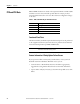
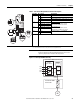
Table 2 - Safe Torque Off Option Board Terminal Descriptions
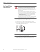
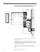
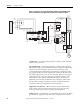
Figure 1 - Safe Torque Off Drive Circuitry
Term. Blk. No. Signal Description
X5 1 SD1+ Isolated Disable input 1 +24V +/-20% 10... 15 mA
2 SD1– Virtual GND 1
3 SD2+ Isolated Disable input 2 +24V +/-20% 10... 15 mA
4 SD2– Virtual GND 2
X2
(1)
21 Digital Out 1 - N.C. Max. Resistive Load:
240V AC / 30V DC - 1200 VA, 150 W
Max. Current: 5A, Min. Load: 10 mA
Max. Inductive Load:
240V AC / 30V DC - 8400 VA, 105 W
Max. Current: 3.5 A, Min. Load: 10 mA
22 Digital Out 1 Common
23 Digital Out 1 - N.O.
X3
(1)
25 Digital Out 2 Common
26 Digital Out 2 N.O.
X7
(1)
28 TI1+ Thermistor input: R
trip
≥ 4.0 kΩ (PTC)
29 TI1–
(1) This terminal block is not used as part of the Safe Torque Off function.
21 22 23
25 26
1 2 3 4
28 29
ON OFF
X10
X5
X2
X3
X7
IMPORTANT
The drive will not run unless a wire is installed in the hardware
thermistor input (X7-28 and X7-29) and the thermistor short circuit
supervisor jumper X10 is installed in the OFF position.
PowerFlex 700H Control Unit
PowerFlex 700H
Power Unit
PWM
Control
M
Micro-
controller
Hardware
Safe-Off 1
Hardware
Safe-Off 2
SD1+
SD1-
SD2+
SD2-
=
3~
Safe-Off
Option Board