User Manual PowerFlex 700H AC Drive Safe Torque Off Option Catalog Number 20C-DG01
Important User Information Solid-state equipment has operational characteristics differing from those of electromechanical equipment. Safety Guidelines for the Application, Installation and Maintenance of Solid State Controls (publication SGI-1.1 available from your local Rockwell Automation sales office or online at http://www.rockwellautomation.com/literature/) describes some important differences between solid-state equipment and hard-wired electromechanical devices.
Summary of Changes This manual contains new and updated information. New and Updated Information This table contains the changes made to this revision. Topic Page All instances of the term “Safe-Off” are changed to the term “Safe Torque Off” Throughout manual Added applicable machinery safety standards to Safety and Machinery Standards. 8 Removed Safety Certificate Examples and provided new link to online certificates. 8 Added new Important Safety Considerations section.
Summary of Changes 4 Rockwell Automation Publication 20C-UM001B-EN-P - June 2011
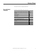
Table of Contents Summary of Changes New and Updated Information. . . . . . . . . . . . . . . . . . . . . . . . . . . . . . . . . . . . . . 3 Chapter 1 Overview What is the Safe Torque Off Option? . . . . . . . . . . . . . . . . . . . . . . . . . . . . . . . . 7 Safety of Machinery Standards . . . . . . . . . . . . . . . . . . . . . . . . . . . . . . . . . . . . . . 8 Certified Equipment . . . . . . . . . . . . . . . . . . . . . . . . . . . . . . . . . . . . . . . . . . . . . . .
Table of Contents 6 Rockwell Automation Publication 20C-UM001B-EN-P - June 2011
Chapter 1 Overview The PowerFlex 700H control board, 24V DC Digital Input with Analog I/O (20C-DA1-A) board, and the Safe Torque Off option board (20C-DG01), when used with other safety components, helps provide a hardware-based safe torque off to prevent torque on the motor shaft. The Safe Torque Off option is just one component in a safety control system. Components in the system must be chosen and applied appropriately to achieve the desired level of operator safeguarding.
Chapter 1 Overview Safety of Machinery Standards The Safe Torque Off option is compliant with the following safety standards: • EN 60204-1:2006 Safety of Machinery – Electrical equipment of machines – Part 1: General Requirements • EN ISO 13849-1:2008 Safety of Machinery – Safety-related parts of control systems - Part 1: General Principles for Design • EN ISO 13849-2:2003 Safety of Machinery – Safety-related parts of control systems – Part 2: Validation • EN 61800-5-2:2007 Adjustable Speed Electrical Po
Overview Important Safety Considerations Chapter 1 The system user is responsible for: • the set-up, safety rating, and validation of any sensors or actuators connected to the system. • completing a system-level risk assessment and reassessing the system any time a change is made. • certification of the system to the desired safety performance level. • project management and proof testing.
Chapter 1 Overview PL d/Category 3 Performance Definition To achieve PL d/category 3 according to EN ISO 13849-1, the safety-related parts have to be designed such that: • the safety-related parts of machine control systems and/or their protective equipment, as well as their components, shall be designed, constructed, selected, assembled, and combined in accordance with relevant standards so that they can withstand expected conditions. • well tried safety principles shall be applied.
Overview System Performance Level and Safety Integrity Level (SIL) Chapter 1 For safety-related control systems, Performance Level (PL), according to EN ISO 13849-1, and SIL levels, according to IEC 61508 and EN 62061, include a rating of the system’s ability to perform its safety functions. All of the safety-related components of the control system must be included in both a risk assessment and the determination of the achieved levels.
Chapter 1 Overview PFD and PFH Data PFD and PFH calculations are based on the equations from Part 6 of IEC 61508 and show worst-case values. This table provides data for a 20-year proof test interval and demonstrates the worst-case effect of various configuration changes on the data. Table 1 - PFD and PFH for 20-year Proof Test Interval Attribute Test Result PFDav 1.52 x 10⁻³ PFH 1.
Chapter 2 Installation and Wiring Installation must be in accordance with the following steps and must be carried out by suitably competent personnel. The Safe Torque Off option board (device) is intended to be part of the safety related control system of a machine. Before installation, a risk assessment should be performed to determine whether the specifications of this device are suitable for all foreseeable operational and environmental characteristics of the machine to which it is to be fitted.
Chapter 2 Installation and Wiring Safe Torque Off Option Board Installation ATTENTION: To avoid an electric shock hazard, verify that the voltage on the bus capacitors has discharged completely before servicing. Check the DC bus voltage at the Power Terminal Block by measuring between the +DC and -DC terminals, between the +DC terminal and the chassis, and between the -DC terminal and the chassis. The voltage must be zero for all three measurements.
Installation and Wiring Chapter 2 5. Remove the I/O board in Slot B (if present). Do not remove enclosure cover. Enclosure is illustrated without the cover for clarity. = 6. Install the new Safe Torque Off option board (20C-DG1) in Slot B.
Chapter 2 Installation and Wiring Wire the Safe Torque Off Option The Safe Torque Off option disables the drive’s output IGBT’s by disconnecting the gate control power supply (see Figure 1 on page 17). The system satisfies the requirements of EN ISO 13849-1 PL d/Category 3 for Safe Torque Off and protection against restart. Under normal drive operation, the Safe Torque Off inputs (SD1 and SD2) are energized and gate control power is available to the gate control circuit.
Installation and Wiring Chapter 2 Table 2 - Safe Torque Off Option Board Terminal Descriptions ON OFF Term. Blk. No. Signal X5 1 SD1+ 2 SD1– 3 SD2+ 4 SD2– 21 Digital Out 1 - N.C. X2 (1) 22 Digital Out 1 Common 23 Digital Out 1 - N.O. 25 Digital Out 2 Common X3 (1) 26 Digital Out 2 N.O. X10 X7 (1) 28 29 25 28 29 TI1+ TI1– Description Isolated Disable input 1 +24V +/-20% 10... 15 mA Virtual GND 1 Isolated Disable input 2 +24V +/-20% 10... 15 mA Virtual GND 2 Max.
Chapter 2 Installation and Wiring Figure 2 - Example 1 - Drive Safe Torque Off Connections with Coast-to-Stop Action and Emergency Stop Operation, Dual Channel, without External Relay AC Line Input Power PowerFlex 700H AC Drive +24VDC GuardMaster Trojan 24V Com Stop Stop Start Start DigIn Com E-Stop Latching Button Gate Enable Safe-Off Option Board 1 SD1+ 2 SD13 SD2+ 4 SD2- Gate Control Circuit M Circuit Status – Circuit shown with guard door and E-stop closed and system ready for normal operatio
Installation and Wiring Chapter 2 Application Considerations – When the hazard analysis for the overall machine determines the need for external mechanical brakes or other stopping means, the external means shall be activated after the removal of power for Stop Category 0. When used, the E-stop button must utilize direct-opening contacts. The button must latch to an open state when the contacts open. The button must be red with a yellow background.
Chapter 2 Installation and Wiring Figure 3 - Example 2 - Drive Safe Torque Off Connections with Controlled Stop Action and Emergency Stop Operation, Dual Channel, with External Relay AC Line Input Power PowerFlex 700H AC Drive GuardMaster Trojan +24VDC 24V Com Stop Stop E-Stop Latching Button Start Start DigIn Com +24V DC A1 S21 S11 S52 S12 S22 37 47 57 13 23 S33 S34 Safe-Off Option Board Minotaur MSR138DP A2 X1 X2 X3 X4 Y39 Y40 38 48 58 Gate Enable 1 SD1+ 14 24 Y2 Y1 2 SD13 SD2+ 24V DC C
Installation and Wiring Chapter 2 Torque Off option board when the gate is opened. A single fault detected on the Minotaur safety input circuits will result in the lock-out of the system to a safe state (off ) at the next operation and will not cause loss of the safety function. Each of the inputs on the Safe Torque Off option board independently monitors the status of the safety circuit and the status of the other input on the board.
Chapter 2 Installation and Wiring 4. Both “Gate Disable” bits, 10 in [Fault Config1] and 15 in [Alarm Config1], are set: The Gate Disable fault takes precedence. Installation Checklist The following items must be completed when installing and configuring the Safe Torque Off option for PowerFlex 700H drives.
Installation and Wiring Verify Operation Chapter 2 At regular intervals during the life of the machine check the safety function for proper operation. Both safety channels shall be verified. How frequently the safety function is checked is dependent on the safety analysis of the machine section controlled by the drive.
Chapter 2 Installation and Wiring Notes: 24 Rockwell Automation Publication 20C-UM001B-EN-P - June 2011
Index Numerics 24V DC digital input with analog I/O (20CDA1-A) option board 7 A alarm configuration 21 L low demand mode definition 11 O option board 24V DC digital input with analog I/O (20CDA1-A) 7 C coast-to-stop action and emergency stop operation connection example 18 controlled stop action and emergency stop operation connection example 20 D definition high demand/continuous mode 11 low demand mode 11 performance level 11 PFD 11 PFH 11 stop category 0 10 stop category 1 10 drive circuitry diagram
Index 26 Rockwell Automation Publication 20C-UM001B-EN-P - June 2011
Rockwell Automation Support Rockwell Automation provides technical information on the Web to assist you in using its products. At http://www.rockwellautomation.com/support/, you can find technical manuals, a knowledge base of FAQs, technical and application notes, sample code and links to software service packs, and a MySupport feature that you can customize to make the best use of these tools.