
Owner manual


Rockwell Automation Publication 20B-IN028B-EN-P - August 2014 3
Replacing a Balancing Resistor on a PowerFlex 700 Drive, Frames 8, 9, and 10
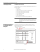
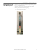
Locating the Balancing
Resistor
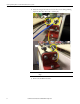
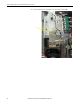
The balancing resistor is secured to the DC+ bus bar. This image provides a
close-up view of a balancing resistor (on a frame 8 drive).
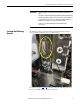
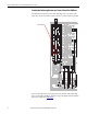
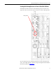
The sections on pages 4
, 5, and 6 show where to find the balancing resistor on a
frame 8, 9, and 10 PowerFlex 700 drive, respectively.
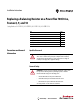
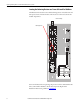
IMPORTANT
The Catalog Number (Cat. No.), in this case 20B, identifies a PowerFlex 700
drive.
The Voltage Code and Current Rating should match the information identified
in Product Safety Advisory (PSA) #2014-06-002. Voltage codes C and D indicate
an AC input drive. Voltage codes H, J, P, and R indicate a DC input drive. This
information is necessary to select the correct replacement kit.
Frames 8, 9, or 10 identify PowerFlex 700 drives affected by PSA
#2014-06-002.