
Owner manual


Rockwell Automation Publication 20B-IN028B-EN-P - August 2014 15
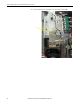
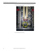
Replacing a Balancing Resistor on a PowerFlex 700 Drive, Frames 8, 9, and 10
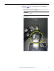
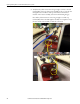
10. Remove the lugs from the resistor terminals and, using an 18 AWG wire
crimper for a non-insulated connector, crimp the wires to the lugs.
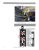
11. Secure the lug with the black resistor wire to the left terminal (R1) on the
bottom of the resistor assembly.
12. Secure the lug with the blue resistor wire to the right terminal (R3) on the
bottom of the resistor assembly.
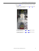
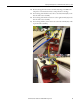
13. Secure the lug with the yellow resistor wire to the left terminal (R2) on the
top of the resistor assembly.