Installation Instructions Replacing a Balancing Resistor on a PowerFlex 700 Drive, Frames 8, 9, and 10 Catalog Numbers SK-G1-RB1-F8, SK-G1-CBRB1-F8, SK-G1-RB1-F910, SK-G1-CBRB1-F910 Topic Precautions and General Information Page Precautions and General Information 1 Commonly Used Tools 2 Identifying Information on the PowerFlex 700 Drive Nameplate 2 Locating the Balancing Resistor 3 Replacing the DC+ Bus Bar with a Balancing Resistor 7 Additional Resources 17 Qualified Personnel ATTENTION: O
Replacing a Balancing Resistor on a PowerFlex 700 Drive, Frames 8, 9, and 10 Commonly Used Tools Installation and Service Tools The following list covers the tools needed for replacing the balancing resistor on a PowerFlex® 700 drive. • Ohm meter • T20 Torx driver • Torque wrench with 2.3…23.7 N•m (20…210 lb•in) range • 10 mm socket wrench (must fit torque wrench) • 17 mm socket wrench (must fit torque wrench) • 17 mm combination wrench • 3/8 in. socket wrench • 5/16 in.
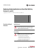
Replacing a Balancing Resistor on a PowerFlex 700 Drive, Frames 8, 9, and 10 IMPORTANT Locating the Balancing Resistor The Catalog Number (Cat. No.), in this case 20B, identifies a PowerFlex 700 drive. The Voltage Code and Current Rating should match the information identified in Product Safety Advisory (PSA) #2014-06-002. Voltage codes C and D indicate an AC input drive. Voltage codes H, J, P, and R indicate a DC input drive. This information is necessary to select the correct replacement kit.
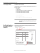
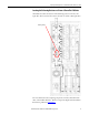
Replacing a Balancing Resistor on a PowerFlex 700 Drive, Frames 8, 9, and 10 Locating the Balancing Resistor on a Frame 8 PowerFlex 700 Drive This illustration shows the location of the balancing resistor on a frame 8 AC input drive. The location of the resistor is the same on a frame 8 DC input drive.
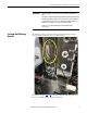
Replacing a Balancing Resistor on a PowerFlex 700 Drive, Frames 8, 9, and 10 Locating the Balancing Resistor on a Frame 9 PowerFlex 700 Drive This illustration shows the location of the balancing resistor on a frame 9 AC input drive. The location of the resistor is the same on a frame 9 DC input drive. Balancing Resistor For more information about replacing components on frame 9 PowerFlex 700 drive, see PowerFlex 700 Drive - Frame 9 Components Replacement Installation Instructions, publication 20B-IN025.
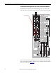
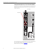
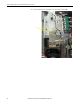
Replacing a Balancing Resistor on a PowerFlex 700 Drive, Frames 8, 9, and 10 Locating the Balancing Resistor on a Frame 10 PowerFlex 700 Drive This illustration shows the location of the balancing resistor on both the AC and DC input versions of a frame 10 drive. The inverter is common to both the AC and DC input drives.
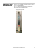
Replacing a Balancing Resistor on a PowerFlex 700 Drive, Frames 8, 9, and 10 Replacing the DC+ Bus Bar with a Balancing Resistor Follow these steps to replace the DC+ bus bar with a single balancing resistor on frame 8, 9, or 10 PowerFlex 700 drive. Note that the replacement part contains both the DC+ bus bar and new balancing resistors (as shown in the following image). 1. Unpack the replacement assembly.
Replacing a Balancing Resistor on a PowerFlex 700 Drive, Frames 8, 9, and 10 2. Verify the rating of the resistors to be sure there was no damaged during shipment (R1 to R2 = R2 to R3 = 6.8 kΩ ±5%). IMPORTANT Do not install the resistor if the measurement is not within the recommended range. 3. Remove the shield from the drive.
Replacing a Balancing Resistor on a PowerFlex 700 Drive, Frames 8, 9, and 10 4. Because the existing resistor wires will be reused, cut the wires off of the resistor at the solder joint, to keep the wires as long as possible. Frame 9 Drive Shown 5. Strip the tip of each wire to approximately 6 mm (0.24 in.).
Replacing a Balancing Resistor on a PowerFlex 700 Drive, Frames 8, 9, and 10 6. Cut and remove the tie wraps that secure the resistor wire bundle.
Replacing a Balancing Resistor on a PowerFlex 700 Drive, Frames 8, 9, and 10 7. Follow steps a…c to remove the existing DC+ bus bar and balancing resistor from the drive. a. Remove the bolts between the right-angled bus bar and the large bus bar (as identified in the following image). IMPORTANT Do not remove the bolts that attach the cables to the right-angled bus bar.
Replacing a Balancing Resistor on a PowerFlex 700 Drive, Frames 8, 9, and 10 b. Remove the two bolts from the bottom of the bus bar (as shown in the following image). c. While holding the bus bar, remove the nuts that secure the bus bar to the chassis and remove the bus bar. IMPORTANT The set screws can come out when a nut is removed.
Replacing a Balancing Resistor on a PowerFlex 700 Drive, Frames 8, 9, and 10 8. Follow steps a…c to install the replacement bus bar and resistor assembly into the drive. a. Install the set screws and nuts removed in step 7c on page 12. Tighten the nuts to 5.65 N•m (50 lb•in). Frame 8 Drive Shown b. Install the bolts removed in step 7b on page 12. Tighten the bolts to 23.5 N•m (208 lb•in). c. Install the bolts removed in step 7a on page 11. Tighten the bolts to 23.5 N•m (208 lb•in).
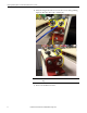
Replacing a Balancing Resistor on a PowerFlex 700 Drive, Frames 8, 9, and 10 9. Verify that the yellow resistor wire is long enough to connect to the left terminal (R2) on the top of the resistor assembly. To do so, route the wire through the bottom and out of the top of the holes in the insulator material on the resistor assembly (as shown in the following images).
Replacing a Balancing Resistor on a PowerFlex 700 Drive, Frames 8, 9, and 10 10. Remove the lugs from the resistor terminals and, using an 18 AWG wire crimper for a non-insulated connector, crimp the wires to the lugs. 11. Secure the lug with the black resistor wire to the left terminal (R1) on the bottom of the resistor assembly. 12. Secure the lug with the blue resistor wire to the right terminal (R3) on the bottom of the resistor assembly. 13.
Replacing a Balancing Resistor on a PowerFlex 700 Drive, Frames 8, 9, and 10 14. Secure the resistor wire bundle below the assembly using tie-wraps (as shown in the following image). 15. Re-install the shield on the drive.
Replacing a Balancing Resistor on a PowerFlex 700 Drive, Frames 8, 9, and 10 Additional Resources These documents contain additional information concerning related products from Rockwell Automation. Resource Description PowerFlex 700 Drive - Frame 8 Components Replacement Installation Instructions, publication 20B-IN024 Provides guidelines for replacing the major components in the PowerFlex® 700 Frame 8 drive.
Rockwell Automation Support Rockwell Automation provides technical information on the Web to assist you in using its products. At http://www.rockwellautomation.com/support you can find technical and application notes, sample code, and links to software service packs. You can also visit our Support Center at https://rockwellautomation.custhelp.com/ for software updates, support chats and forums, technical information, FAQs, and to sign up for product notification updates.