
Installation Instructions - Frames 0â¦6

Rockwell Automation Publication 20B-IN019E-EN-P - July 2013 45
PowerFlex 700 Adjustable Frequency AC Drive – Frames 0…6
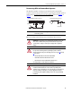
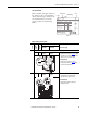
Drive Identification
Refer to the drive nameplate and locate
the “ Vo l t a g e Co d e ,” “ Current R ati n g ,”
“Frame,” and “UL Type” (Frames 5…6).
Use this information to locate the
proper procedure in the following
tables.
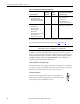
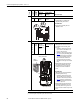
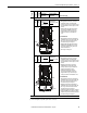
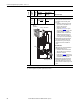
Jumper Settings and Locations
Cat No. 20B D xxx x x xxxxxxx
Made in the USA (TAC 1J)
Rockwell Automation, Mequon WI 53092-4400
UL TYPE 1/IP20
Mfd. in 2007 on Aug 1
Frame: 3
Serial Number: xxxxxxx
Series: B
I/O: 24VAC/DC (Standard)
Original Firmware V. x.xxx
Listed
Ind. Cont
Eq. 966X
U
c
US
L
®
Normal Duty Power
Heavy Duty Power
AC Voltage Range
Amps
Input: 3 Phase, 47-63Hz
Output: 3 Phase, 0-400 Hz
AC Voltage Range
Base Hz (default)
Continuous Amps
1 Min Overload Amps
3 Sec Overload Amps
xxx kW
xxx kW
342-440
xxx
0-400
50 Hz
xxx
xxx
xxx
xxx kW
xxx kW
432-528
xxx
400V 480V
0-460
60 Hz
xxx
xxx
xxx
N223
Voltage Code
Frame
Current Rating
UL Type
Series
Frame
Voltage
Code
Current
Rating
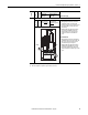
Factory Default Jumper Settings
Power Source Type
MOV/Input
Filter Caps
DC Bus Common
Mode Caps
0…1 All Drives
B…E All PE_B
Installed
PE_A
Installed
Solid Ground
• Remove the I/O Cassette (see page 53
). Verify
that jumpers are installed at the “PE_A” and
“PE_B” locations on the Power Board.
Non-Solid Ground
• Remove the I/O Cassette (see page 53).
Remove jumpers at the “PE_A” and “PE_B”
locations on the Power Board.
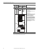
2 B…E All PE_MOV
Installed
PE_CAP
Installed
Solid Ground
• Verify that jumpers are installed at the
“PE_CAP” and “PE_MOV” locations.
Non-Solid Ground
• Remove jumpers at the “PE_CAP” and
“PE_MOV” locations.
BR1
BR2
DC+
DC–
PE
U/T1
V/T2
W/T3
R/L1
S/L2
T/L3
Use 75C Wire Only
#10-#14 AWG
Torque to 7 in-lbs
!
DANGER
PE A
PE B
CM Cap
MOV
BR1 BR2 DC+ DC- U/T1 V/T2 W/T3
SHLD SHLD
PE R/L1 S/L2 T/L3
PE 2
MOV-PE JMPR
PE 1
AUX IN+ AUX OUT–
75C Cu Wire
6 AWG [10MM
2
] Max.
12 IN. LBS.
1.4 N-M
} TORQUE
WIRE
STRIP
CONTROL
POWER
PE 4
PE 3
MOV
PE_MOV
CM Cap
PE_CAP